CompactPCI ® ICP-PIII High-Performance CPU Boards USER’S MANUAL Publication Number: PD00581013.
This user’s manual describes a product that, due to its nature, cannot describe a particular application. The content of this user’s manual is furnished for informational use only, is subject to change without notice, and should not be constructed as a commitment by Inova Computers GmbH. Inova Computers GmbH assumes no responsibility or liability for any errors or inaccuracies that may appear in this user’s manual.
Preface CompactPCI ® ICP-PIII Preface Contents Unpacking and Special Handling Instructions ............................................... 6 Revision History ............................... 7 Three Year Limited Warranty.............. 8 1.0 ICP-PIII CPU ........................... 1-2 1.01 Interfacing ............................................................................................... 1.02 Peripherals .............................................................................................
Preface ICP-PIII 1.4 Hardware ............................. 1-10 1.41 Block Diagram........................................................................................ 1-10 Figure 1.41 Block Diagram ....................................................................................................... 1-10 1.42 Connector Location ............................................................................... 1-11 Figure 1.42 Connector Locations ........................................................
Preface CompactPCI ® ICP-PIII 3.1 CompactPCI Backplane .......... 3-10 Figure 3.10 Inova’s 32-Bit CompactPCI 8-Slot Backplane - RH System Slot ................................ 3-11 3.2 Interfaces ............................. 3-12 3.21 J7 & J12 Fast Ethernet ............................................................................ 3-12 Figure 3.21 RJ45 Pinout ........................................................................................................... 3-12 Table 3.
Preface ICP-PIII A1 IPB-FPE8 CPU Extension ......... A-2 A1.1 J11 Interface for COM1, Mouse & Keyboard ............................................ A-2 A1.2 IPB-FPE8 & Front-panel (4HP or 8HP) ....................................................... A-2 Figure A1.2 IPB-FPE8 Stand-Alone or Integrated with CPU .......................................................... A-2 A1.3 Stand-Alone IPB-FPE8 ............................................................................... A-3 Figure A1.
Preface CompactPCI ® ICP-PIII B1 IPM-ATA CPU Extension ........... B-2 B1.1 J1 Interfaces ............................................................................................. B-2 Figure B1.1a Dedicated IPM-ATA Backplane ................................................................................ B-2 B1.1 J1 Interfaces (Contd.) ............................................................................... B-3 Figure B1.1b The Complete Connection Picture ....................................
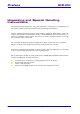
Preface ICP-PIII Unpacking and Special Handling Instructions This product has been designed for a long and fault-free life; nonetheless, its life expectancy can be severely reduced by improper treatment during unpacking and installation. Observe standard antistatic precautions when changing piggybacks, ROM devices, jumper settings etc.
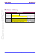
Preface CompactPCI ® ICP-PIII Revision History Revision History Manual MAN-ICP-PIII Publication Number PD00581013.XXX Author Date of Issue PD00581013.001 Preliminary, First Release; All pages revised AB 31/11/2000 PD00581013.002 Updated to include Radeon VE and Rear I/O options AB 15/08/2001 PD00581013.003 Final Version - Included Appendix A-D I/O Modules AB 21/09/2001 PD00581013.004 Specs. Updated & Rear I/O Table Corrected AB 15/02/2002 Issue Doc. PD00581013.
Preface ICP-PIII Three Year Limited Warranty Inova Computers (‘Inova’) grant the original purchaser of Inova products the following hardware warranty. No other warranties that may be granted or implied by anyone on behalf of Inova are valid unless the consumer has the expressed written consent of Inova. Inova warrants their own products (excluding software) to be free from defects in workmanship and materials for a period of 36 consecutive months from the date of purchase.
CompactPCI ® ICP-PIII Product Overview 1 Product Overview Overview Contents 1.0 ICP-PIII CPU ........................... 1-2 1.01 Interfacing ............................................................................................... 1.02 Peripherals ............................................................................................... 1.03 Software .................................................................................................. 1.04 Graphics .............................
Product Overview ICP-PIII 1.0 ICP-PIII CPU The ICP-PIII is a high-performance 3U CompactPCI single-board Socket 370 based universal CPU that satisfies the needs of a wide range of industrial automation, military, medical, aerospace, imaging, telecommunications, process control and embedded/OEM applications. The powerhouse in any application, Inova’s Socket 370 based high-performance 3U CompactPCI CPU is packed with a feature set unheard of on such a small scale.
CompactPCI ® ICP-PIII Product Overview 1.01 Interfacing For maximum communication flexibility, multiple interfaces satisfying different industrial standards are implemented. LAN applications can take advantage of Inova’s 10BaseT/100BaseTx (dual) Ethernet implementation or, if high-speed system-level serial interfacing is required, the built-in 400/100 Mbit/s FireWire port is available.
Product Overview ICP-PIII 1.1 Specifications Processor Socket 370 BGA (mobile) or FC-PGA based Intel Pentium III or Celeron Pentium III Up to 1000MHz (100MHz PSB, 256kByte L2 cache) Mobile PIII Up to 700MHz BGA2 package with interposer (100MHz PSB, 256kByte L2 cache) Mobile Celeron BGA2 package with interposer (100Mz PSB, 128kByte L2 cache) L2 Cache 128/256kByte L2 cache depending on processor Memory 128MByte soldered synchronous DRAM with optional BIOS activated ECC feature.
Product Overview CompactPCI ® ICP-PIII PCI/PCI Intel 21150 transparent bridge (Master) or Intel 21554 non-transparent PCI/PCI bridge for multiprocessing (Slave) operation with Basic Hot-Swap support (PICMG 2.1 R1.0), Serialized interrupts and universal (3.3/5.0V) V I/O support On-Board I/O A A A A Rear I/O Standard to all CPU variants is option ‘C’ which provides 2nd FireWire channel, 2nd USB channel, LPT1 (Floppy), EIDE and loudspeaker. Other I/O configurations including customized are possible.
Product Overview ICP-PIII 1.2 Configuration Inova’s high-performance, high-density 3U PIII board supports functionality and connectivity on all three major serial networking levels like Fast Ethernet, FireWire and USB as well as most state-ofthe-art fieldbus standards such as PROFIBUS, CAN, Interbus, and LON.
Product Overview CompactPCI ® ICP-PIII Figure 1.
Product Overview ICP-PIII 1.3 Software 1.31 Linux Being a modern operating system, Linux executes a 32-bit architecture, uses pre-emptive multitasking, has protected memory, supports multiple users, and has rich support for networking, including TCP/IP. Linux was originally written for Intel’s 386 architecture, but now runs on a wide variety of hardware platforms including the full x86 family of processors as well as Alpha, SPARC, and PowerPC.
CompactPCI ® ICP-PIII Product Overview 1.34 Windows CE Microsoft® Windows CE is an operating system designed for a wide variety of embedded systems and products, from hand-held PCs and consumer electronic devices to specialized industrial controllers and embedded communications devices.
Product Overview ICP-PIII 1.4 Hardware 1.41 Block Diagram Figure 1.
Product Overview CompactPCI ® ICP-PIII 1.42 Connector Location 1 Figure 1.42 Connector Locations J4 KEY J1 J3 J6 CPCI-CONNECTOR J2 J16 PENTIUM III J18 J13 J11 J10 J9 J14 J17 J19 J15 J7 J20 1.43 Connector Description Table 1.
Product Overview ICP-PIII Table 1.43 Continued Connector Description J9, J10 Hard Disk Interface J11 COM1, Keyboard and Mouse Interfaces J13 COM2 and LPT1 Interfaces J141) FLASH Extension Piggyback Connector for up to 288MBytes J15 FireWire Interface J16 TFT Flat-Panel, PanelLink™ or GigaSTAR Interface J17 15-Pin High Density D-Sub VGA Graphics Interface J18 1.
CompactPCI ® ICP-PIII Product Overview Figure 1.44 Front-Panel Options 1 The front-panels shown in Figure 1.44 show the tremendous flexibility built into Inova’s CPU concept. From left, the standard CPU is 4TE with Ethernet, FireWire, USB and VGA graphic connections. If, instead of VGA graphics, PanelLink is required then the piggyback is installed on J14 for this purpose.
Product Overview ICP-PIII 1.45 Interface Positions Figure 1.45 Interfaces SDRAM EXTENSION KEY CPCI-CONNECTOR PENTIUM III FLASH-DISK FLASH-MEMORY Figure 1.45 shows the typical positioning of the front panel extension modules for mouse, keyboard, COM1, COM2, LPT1 and COM2/Fieldbus interfaces. Note A hard disk, if installed, will generally be fitted to the piggyback containing the mouse, keyboard, COM1 and COM2 interfaces. Page 1-14 ©2002 Inova Computers GmbH Doc. PD00581013.
CompactPCI ® ICP-PIII Configuration Configuration 2 Configuration Contents 2.0 Memory Map ........................... 2-2 Figure 2.00 System Architecture ................................................................................................. 2-2 Table 2.00 UMB Reservations for ISA ......................................................................................... 2-3 Table 2.01 Port Addressing ...............................................................................................
Configuration ICP-PIII 2.0 Memory Map Figure 2.
Configuration CompactPCI ® ICP-PIII Table 2.00 UMB Reservations for ISA UMB Reservations for ISA Start Address Finish Address 0CC00h 0CFFFh 0D000h 0D3FFh 0D400h 0D7FFh 0D800h 0DBFFh 0DC00h 0DFFFh 2 Table 2.01 Port Addressing Port Addressing Port Doc. PD00581013.
Configuration ICP-PIII 2.1 I/O Mapped Peripherals The original PC-XT and PC-AT desktop computer (ISA bus) specification allows for 10-bit I/O addressed peripherals. This permits peripheral boards to be I/O mapped from 0h to 3FFh. CompactPCI systems permit the full 16-bit addressing capability of the Intel 80x86 ‘processors, from 0h to 0FFFFh.
Configuration CompactPCI ® ICP-PIII Note: *) Denotes Plug ‘n’ Play devices that are configured during the BSP POST. Values shown are ISA compatible I/O addresses for reference only. 2 2.2 Memory Mapped Peripherals PC-AT desktop computers (ISA bus) allow 24-bit memory addressed peripherals. This decoding permits peripheral boards to be mapped in the Intel 80x86 memory map from 0h to 0FFFFFFh.
Configuration ICP-PIII Table 2.
Configuration CompactPCI ® ICP-PIII 2.4 Inova PIII Device List Table 2.40 shows the available PCI devices both on-board and off-board (CompactPCI backplane). It should be noted that the interrupt routing assumes a standard Inova backplane configuration with a right-hand system slot. 2 Table 2.
Configuration ICP-PIII 2.5 Interrupt Configuration The CompactPCI specification defines a total of six interrupt signals on the backplane. INTA# through INTD# are used to route interrupts from the CompactPCI boards to the PIC on the ‘processor board. The interrupt request level generated by the device depends on the backplane slot number which the board is plugged into, and the interrupt signal which is driven by the particular PCI device.
Configuration CompactPCI ® ICP-PIII 2.6 Timer / Counter The IBM-compatible architecture configures the programmable timer / counter (Intel 8254-compatible) devices for system-specific functions as shown in Table 2.50. The BIOS programs Timer 0 to generate an interrupt approximately every 55ms (18.2 times per second.) This interrupt, known as the system timer tick, updates the BIOS clock and turns off the floppy disk motor drive after a few seconds of inactivity for example.
Configuration ICP-PIII This page has been left blank intentionally. Page 2-10 ©2002 Inova Computers GmbH Doc. PD00581013.
Interfaces CompactPCI ® ICP-PIII Interfaces Interfaces Contents 3.0 CompactPCI J1/J2 Connector ... 3-3 3.01 CompactPCI Connector ........................................................................... 3-3 Figure 3.01 The 32-Bit CompactPCI Bus Interface Connector ...................................................... 3-3 3.02 ICP-PIII Connector J1 and J2 ..................................................................... 3-3 Table 3.02 Inova’s ICP-PIII 32-Bit CompactPCI J1 Pin Assignment .........
Interfaces ICP-PIII 3.29 J14 FLASH Interface ................................................................................ 3-19 3.30 J18 Floppy Disk Interface ........................................................................ 3-19 3.31 Connecting the PIII to the Inova IPB-FPE8 .............................................. 3-20 Figure 3.31 CPU to IPB-FPE8 Connection .................................................................................. 3-20 3.
Interfaces CompactPCI ® ICP-PIII 3.0 CompactPCI J1/J2 Connector The CompactPCI standard is electrically identical to the PCI local bus standard but has been enhanced to support rugged industrial environments and up to 8 slots. The standard is based upon a 3U board size and uses a rugged pin-in-socket hard 2mm connector (IEC-1076-4-101.) 3.01 CompactPCI Connector Figure 3.01 The 32-Bit CompactPCI Bus Interface Connector 1 11 15 3 25 e d c b a PCB 3.
Interfaces ICP-PIII Table 3.02 Inova’s ICP-PIII 32-Bit CompactPCI J1 Pin Assignment Pin Nr J1-25 Row A Row B Row C Row D +5V REQ64# PullUp V( I / O ) Row E ENUM# +3.3V +5V J1-24 AD[1] +5V V( I / O ) AD[0] ACK64# PullUp V( I / O ) J1-23 +3.3V AD[4] AD[3] +5V AD[2] J1-22 AD[7] GND +3.3V AD[6] AD[5] J1-21 +3.3V AD[9] AD[8] M66EN – Gnd C / BE[0]# J1-20 AD[12] GND V( I / O ) AD[11] AD[10] J1-19 +3.3V AD[15] AD[14] GND AD[13] J1-18 SERR# GND +3.
Interfaces Table 3.
Interfaces ICP-PIII Table 3.
Interfaces Table 3.
Interfaces ICP-PIII Table 3.
Interfaces CompactPCI ® ICP-PIII Table 3.
Interfaces ICP-PIII 3.1 CompactPCI Backplane The form factor defined for CompactPCI boards is based upon the Euro-card industry standard. Both 3U (100 mm by 160 mm) and 6U (233 mm by 100 mm) board sizes are defined. A CompactPCI system is composed of up to eight CompactPCI cards. The CompactPCI backplane consists of one System Slot, and up to seven Peripheral Slots. The System Slot provides arbitration, clock distribution, and reset functions for all boards on the bus.
Interfaces CompactPCI ® ICP-PIII Figure 3.10 Inova’s 32-Bit CompactPCI 8-Slot Backplane - RH System Slot 3 ZABCDEF ZABCDEF ZABCDEF ZABCDEF ZABCDEF ZABCDEF ZABCDEF ZABCDEF Note: The logical slots are different to the physical slots. The slot marked with the ‘g‘ is the System Slot and always assigned logical ‘0’. The neighbouring slot is logical ‘0xF’! Doc. PD00581013.
Interfaces ICP-PIII 3.2 Interfaces 3.21 J7 & J12 Fast Ethernet J7 is available as standard on the CPU front-panel and, as an option, J12 may also be available but at the expense of the FireWire interface. The RJ45 interface supports both the 10BaseT and 100BaseTX twisted pair standard. Figure 3.21 RJ45 Pinout Activity Link 8 1 Table 3.21 Ethernet Connector Signals Pin No.
Interfaces CompactPCI ® ICP-PIII 3.22 J17 VGA Interface J17 is available on the CPU front-panel if this option is required and if this position is not already occupied by a PCI, PanelLink or GigaST)R piggyback. The 15-pin high-density D-Sub connector forms the physical interface for the video on the ICP-PIII which is based on either the Silicon Motion Lynx3DM graphic accelerator equipped with 8MByte RAM or the Radeon VE controller with 16MByte RAM.
Interfaces ICP-PIII Table 3.22b Video Resolutions Lynx3DM Controller Colour Depth 65, 000 16.
Interfaces CompactPCI ® ICP-PIII 3.23 J16 PanelLink Interface J16 is available if requested at time of order and replaces the standard VGA connector on the frontpanel. Figure 3.23 PanelLink Interface Connector 5 1 10 3 6 15 11 Table 2.12 PanelLink Interface Pin No. 1 Tx2- 2 Tx1- 3 Tx0- 4 TxC- 5 DDC Data 6, 7, 8, 9 Doc. PD00581013.
Interfaces ICP-PIII 2.24 J16 GigaSTAR Interface The standard 9-pin D-Sub connector is used for GigaSTAR video transmission. Figure 2.24 GigaSTAR D-Sub Interface Pinout 1 5 6 9 Table 2.11 GigaSTAR Interface Pin No. Page 3-16 Signal 1 GigaSTAR Tx+ 2 N/C 3 N/C 4 N/C 5 N/C 6 GigaSTAR Tx- 7 N/C 8 N/C 9 N/C ©2002 Inova Computers GmbH Doc. PD00581013.
Interfaces CompactPCI ® ICP-PIII 3.25 J19 USB Interface J19 is located as standard on the front panel Figure 3.25 USB Interface Pinout 3 1 2 3 4 Table 3.25 USB Connector Signals Pin No. 1 +5V 2 USB P0- 3 USB P0+ 4 GND Housing Doc. PD00581013.
Interfaces ICP-PIII 3.26 J15 FireWire Interface J15 is located on the front panel (if this option is available) Figure 3.26 FireWire Interface Pinout 2 4 6 1 3 5 Table 3.26 FireWire Connector Signals Pin No. 1 IEEE 1394 S +12V 2 IEEE 1394 S GND 3 IEEE 1294 S TPB- 4 IEEE 1394 S TPB+ 5 IEEE 1394 S TPA- 6 IEEE 1394 S TPA+ Housing Page 3-18 Signal ( 1A Fuse) PE ©2002 Inova Computers GmbH Doc. PD00581013.
Interfaces CompactPCI ® ICP-PIII 3.27 J20 Infrared (iRdA) Interface This option is proprietary and not documented here. 3.28 J20 Reset Button The reset button allows the CPU to be rest in the event that it ‘hangs’ Performing a reset in this manner is known as a ‘warm’ start as power is not removed from the peripherals (IDE etc.) This reset button is also used when recovering a corrupt BIOS image - refer to the PIII BIOS user’s manual for details. 3.
Interfaces ICP-PIII 3.31 Connecting the PIII to the Inova IPB-FPE8 Appendix A provides more information on the IPB-FPE8 and its derivatives. Figure 3.31 shows how the CPU connects to the piggyback by a length of flex-cable. Figure 3.31 CPU to IPB-FPE8 Connection J4 J6 J3 PENTIUM III J18 J13 J11 J14 J10 J9 Page 3-20 ©2002 Inova Computers GmbH Doc. PD00581013.
Interfaces CompactPCI ® ICP-PIII 3.32 Connecting the PIII to the Inova ICP-HD-1 Appendix B provides more information on the ICP-HD-1 and its derivatives. Figure 3.32 shows how the CPU connects to the piggyback by lengths of flex-cable. Figure 3.32 CPU to ICP-HD-1 Connection 3 J10A J9A J10 J11 J13A J9 J13 J4 J6 J3 PENTIUM III J18 J13 J11 J14 J10 J9 Doc. PD00581013.
Interfaces ICP-PIII 3.33 Connecting the PIII to the Inova IPB-FPE12 Appendix C provides more information on the IPB-FPE12 and its derivatives. Figure 3.33 shows how the CPU connects to the piggyback by a length of flex-cable. The illustration also shows the IPB-FPE8 connection (Appendix A) Figure 3.33 CPU to IPB-FPE12 Connection J13 J4 J6 J3 PENTIUM III J18 J13 J11 J14 J10 J9 Page 3-22 ©2002 Inova Computers GmbH Doc. PD00581013.
Interfaces CompactPCI ® ICP-PIII 3.34 Connecting the PIII to the Inova IPB-FPE12 Appendix C provides more information on the IPB-FPE12 and its derivatives. Figure 3.34 shows how the CPU connects to the piggyback by a length of flex-cable. The illustration also shows the ICP-HD-1 connection (Appendix B) Figure 3.34 CPU to IPB-FPE12 Connection J13 3 J10A J9A J10 J9 J13A J13 J11 J4 J6 J3 PENTIUM III J18 J13 J11 J14 J10 J9 Doc. PD00581013.
Interfaces ICP-PIII 3.35 Connecting the PIII to the ICP-FD-1 Figure 3.35 shows how the CPU connects to the slim-line floppy disk unit. Figure 3.35 CPU to Slim-Line Floppy Disk Connection Floppy J4 J6 J3 J18 PENTIUM III J13 J11 J14 J10 J9 Page 3-24 ©2002 Inova Computers GmbH Doc. PD00581013.
IPB-FPE8 CompactPCI ® Appendix A IPB-FPE8 IPB-FPE8 Contents A1 IPB-FPE8 CPU Extension ......... A-2 A1.1 J11 Interface for COM1, Mouse & Keyboard ............................................ A-2 A1.2 IPB-FPE8 & Front-panel (4HP or 8HP) ....................................................... A-2 Figure A1.2 IPB-FPE8 Stand-Alone or Integrated with CPU .......................................................... A-2 A1.3 Stand-Alone IPB-FPE8 ................................................................
IPB-FPE8 Appendix A A1 IPB-FPE8 CPU Extension The IPBFPE8 provides additional CPU functionality in the form of PS-2 style mouse and keyboard connectors and a serial COM1 port. A1.1 J11 Interface for COM1, Mouse & Keyboard The control of the mouse, keyboard and COM1 interfaces is performed through the J11 connector on the CPU base board. The location of this connector may be determined by referring to Section 1 - Product Overview of the CPU User’s Manual.
IPB-FPE8 CompactPCI ® Appendix A A1.3 Stand-Alone IPB-FPE8 Figure A1.3 illustrates the construction of the stand-alone IPB-FPE8 piggyback and the underside location of the J11 connector. Care should be taken to ensure that pin 1 of J11 on the CPU base board is linked by an appropriate length of flex cable to pin 1 on the piggyback. To help with the orientation, the connector flanks that are blue indicate the blue face of the flex-cable. Unmarked flanks indicate the metallic connection of the flex-cable.
IPB-FPE8 Appendix A A1.4 IPB-FPE8MS (Theme Variation) Figure A1.4 illustrates the construction of the IPB-FPE8MS - a variation of the IPB-FPE8 but with a number of extra features. The electrical connection to the CPU base board is still via the underside connector J11 and again, the precautions mentioned for the IPB-FPE8 are valid here. Figure A1.
IPB-FPE8 CompactPCI ® Appendix A A1.5 IPB-FPE8MS Description As mentioned previously, the IPB-FPE8MS has a number of additional features compared to the standard IPB-FPE8 module. These extra features include HD and FD connection with both standard connectors and the Inova flex cables. This provides the user with system flexibility. Figure A1.
IPB-FPE8 Appendix A A1.6 Keyboard Interface A front-panel with COM1, COM2 mouse and keyboard interfaces is either integrated into an 8HP standard CPU front-panel or available as a separate 4HP unit. The piggyback located behind these interfaces connects to the CPU-mounted J11 connector. Figure A1.6 Keyboard Interface Pinout 5 6 3 4 1 2 Table A1.6 Keyboard Connector Signals Pin No. Signal Pin No. Signal 1 Data 2 N/C 3 GND 4 +5V 5 CLK 6 N/C A1.
IPB-FPE8 CompactPCI ® Appendix A A1.8 COM1 Interface The COM1 port features a complete set of handshaking and modem control signals, maskable interrupt generation and high-speed data transfer rates. A front-panel with COM1, mouse and keyboard interfaces is either integrated into an 8HP standard CPU front-panel or available as a separate 4HP unit. The piggyback located behind these interfaces connects to the CPU-mounted J11 connector. Figure A1.8 COM1 Interface Pinout 1 5 6 9 Table A1.
IPB-FPE8 Appendix A This page has been left blank intentionally.
ICP-HD CompactPCI ® Appendix B ICP-HD ICP-HD Contents B1 ICP-HD CPU Extension ............. B-2 B1.1 J11, J13 Interfaces .................................................................................... B-2 B1.2 ICP-HD-1 & Front-panel (4HP or 8HP)...................................................... B-2 Figure B1.2 ICP-HDE8 Stand-Alone or Integrated with CPU......................................................... B-2 B1.3 IDE Carrier Board ICP-HD-1 .................................................
ICP-HD Appendix B B1 ICP-HD CPU Extension Several hard-disk connection possibilities exist of which two are documented here. Both of these provide additional CPU functionality in the form of PS-2 style mouse and keyboard connectors and serial COM1 and COM2 ports. B1.1 J11, J13 Interfaces The control of the mouse, keyboard, COM1 & COM2 interfaces is performed through the J11 and J13 connectors respectively on the CPU base board.
ICP-HD CompactPCI ® Appendix B B1.3 IDE Carrier Board ICP-HD-1 Figure B1.3 illustrates the construction of the stand-alone ICP-HD1 carrier and the underside location of the J11 & J13 connectors. The same mechanical construction applies to the integrated version. Care should be taken to ensure that pin 1 of J11/J13 on the CPU base board is linked by an appropriate length of flex cable to pin 1 on the carrier.
ICP-HD Appendix B Table B1.3 ICP-HD-1 Connector Description Connector Description J9, J10 Primary IDE (Master / Slave) J9a, J10a Primary IDE (Master / Slave) J11 COM1, Mouse & Keyboard J13 LPT1 & COM2 J13a LPT1 & COM2* B1.4 ICP-HDE8MS (Theme Variation) Figure B1.4 illustrates the construction of the ICP-HDE8MS - a variation of the ICP-HD-1 but with a number of extra features.
ICP-HD Appendix B CompactPCI ® Table B1.
ICP-HD Appendix B B1.5 ICP-HDE8MS Description As mentioned previously, the ICP-HDE8MS has a number of additional features compared to the standard ICP-HD-1 module. These extra features include HD and FD connection with both standard connectors and the Inova flex cables. This provides the user with additional system flexibility. Figure B1.
ICP-HD CompactPCI ® Appendix B B1.6 Keyboard Interface A front-panel with COM1, COM2 mouse and keyboard interfaces is either integrated into an 8HP standard CPU front-panel or available as a separate 4HP unit. The piggyback located behind these interfaces connects to the CPU-mounted J11 connector. Figure B1.6 Keyboard Interface Pinout 5 6 3 4 1 2 Table B1.6 Keyboard Connector Signals Pin No. Signal Pin No. Signal 1 Data 2 N/C 3 GND 4 +5V 5 CLK 6 N/C B1.
ICP-HD Appendix B B1.8 COM1 & COM 2 Interfaces The two COM ports feature a complete set of handshaking and modem control signals, maskable interrupt generation and high-speed data transfer rates. A front-panel with COM1, COM2, mouse and keyboard interfaces is either integrated into an 8HP standard CPU front-panel or available as a separate 4HP unit. The IDE carrier board located behind these interfaces connects to the CPUmounted J11 and J13 connectors. Figure B1.
IPM-ATA CompactPCI ® Appendix B IPM-ATA IPM-ATA B1 IPM-ATA CPU Extension ........... B-2 B1.1 J1 Interfaces ............................................................................................. B-2 Figure B1.1a Dedicated IPM-ATA Backplane ................................................................................ B-2 B1.1 J1 Interfaces (Contd.) ............................................................................... B-3 Figure B1.1b The Complete Connection Picture ..................
IPM-ATA Appendix B B1 IPM-ATA CPU Extension Inova Plug-In Module (IPM-) offers the user the ability to exchange a hard-disk for example without having to remove the CPU from the CompactPCI enclosure and then dismantle it etc. Currently, three units exist that provide industry with hard-disk, Compact FLASH, MicroDrive or ATA PCMCIA mass storage capability. B1.1 J1 Interfaces All IPM-ATA modules possess J1 for data communication between the CompactPCI backplane and the mass storage unit(s) in question.
IPM-ATA CompactPCI ® Appendix B B1.1 J1 Interfaces (Contd.) Standard IDE ribbon-cable is used to connect J2 of the IPB-RIO-HD-FD module to the IPM’s dedicated backplane. The use of ribbon cable permits the mass-storage device(s) to be positioned at any convenient location within the CompactPCI enclosure. Figure B1.1b shows the complete configuration (CompactPCI to IPM-) Figure B1.1b The Complete Connection Picture B KEY: 1. IPM-ATA carrier board 2.
IPM-ATA Appendix B B1.2 IPM-ATA-HD The IPM-ATA-HD has provision for one standard notebook (2.5”) EIDE device (FLASH or hard-disk) and one Compact FLASH or MicroDrive site. Figure B1.2 illustrates the significant connectors for this device while Table B1.2 indicates the jumper positions for the various Master/Slave device configurations. Figure B1.2 IPM-ATA-HD Board Layout 1 2 3 Table B1.
IPM-ATA CompactPCI ® Appendix B B1.3 IPM-ATA-CF The IPM-ATA-CF has provision for one or two standard Compact FLASH or MicroDrive devices. Figure B1.3 illustrates the significant connectors for this device while Table B1.3 indicates the jumper settings for the various Master/Slave device configurations. Figure B1.3 IPM-ATA-CF Board Layout 1 2 3 B Table B1.
IPM-ATA Appendix B B1.4 IPM-ATA-PCMCIA The IPM-ATA-PCMCIA has provision for one standard ATA PCMCIA device and one Compact FLASH or MicroDrive site. Figure B1.4 illustrates the significant connectors for this device while Table B1.4 indicates the jumper settings for the various Master/Slave device configurations. Figure B1.4 IPM-ATA-PCMCIA Board Layout 1 2 3 Table B1.
IPM-ATA CompactPCI ® Appendix B B1.5 Device Compatibility Because of the diversity of Compact FLASH devices available with different architectures and error recovery routines etc. there is a strong possibility that some Master / Slave combinations will fail to be recognised by the BIOS. To help highlight the problem, Inova have provided the test report shown in Table B1.5 which should be regarded as a guide when choosing to pick-and-mix devices.
IPM-ATA Appendix B This page has been left blank intentionally.
IPB-FPE12 CompactPCI ® Appendix C IPB-FPE12 IPB-FPE12 Contents C1 IPB-FPE12 CPU Extension ........ C-2 C1.1 J13 Interface for LPT1 & COM2 ............................................................... C-2 C1.2 IPB-FPE12 & Front-panel (4HP or 12HP) .................................................. C-2 Figure C1.2 IPB-FPE12 Stand-Alone or Integrated with CPU ........................................................ C-2 C1.3 LPT1 & COM2 Piggyback ..........................................................
IPB-FPE12 Appendix C C1 IPB-FPE12 CPU Extension The Inova IPB-FPE12 adds LPT and COM2 functionality to any Inova CPU. The piggyback is available as a stand-alone device with its own 4HP front-panel or integrated within a 12HP K6 or PPC front-panel. The information documented here is valid regardless of the connection choice. C1.1 J13 Interface for LPT1 & COM2 The control of the LPT and COM2 interfaces is performed through the J13 connector on the CPU base board.
IPB-FPE12 CompactPCI ® Appendix C C1.3 LPT1 & COM2 Piggyback Figure C1.3 illustrates the construction of the stand-alone IPB-FPE12 piggyback and the upperside location of the J13 connector. The same mechanical construction applies to the integrated version. Care should be taken to ensure that pin 1 of J13 on the CPU base board is linked by an appropriate length of flex cable to pin 1 on the piggyback.
IPB-FPE12 Appendix C Table C1.3 IPB-FPE12 Connector Description Connector J13 Description LPT1 & COM2 Note: Other Inova piggybacks (ICP-HD-1 & ICPHDE8) provide J13a to “daisy-chain” the LPT1 / COM2 interfaces. If these connectors are used for the integration of the IPB-FPE12 then the COM2 port on these piggybacks is disabled.
IPB-FPE12 CompactPCI ® Appendix C C1.4 LPT1 Interface A front-panel with LPT1 and COM2 interfaces is either integrated into a 12HP standard CPU frontpanel or available as a separate 4HP unit. The piggyback located behind these interfaces connects to the CPU-mounted J13 connector. Figure C1.6 LPT1 Interface Pinout 13 1 25 14 Table C1.6 LPT1 Connector Signals Pin No. CPU Appendix-C Signal Pin No.
IPB-FPE12 Appendix C C1.5 COM2 Interface The COM2 port features a complete set of handshaking and modem control signals, maskable interrupt generation and high-speed data transfer rates. A front-panel with LPT1 and COM2 interfaces is either integrated into a 12HP standard CPU front-panel or available as a separate 4HP unit. The piggyback located behind these interfaces connects to the CPU-mounted J13 connector. Figure C1.5 COM2 Interface Pinout 1 5 6 9 Table C1.5 COM2 Connector Signals Pin No.
IPB-RIO CompactPCI ® Appendix D IPB-RIO IPB-RIO Contents D1 IPB-RIO CPU Extension............ D-2 D1.1 IPB-RIO-HD-FD ....................................................................................... D-2 Figure D1.1 IPB-RIO-HD-FD ....................................................................................................... D-2 D1.2 IPB-RIO-HD-LPT-(FLEX) ........................................................................... D-3 Figure D1.2 IPB-RIO-HD-LPT-(FLEX) .....................
IPB-RIO Appendix D D1 IPB-RIO CPU Extension To enhance the I/O and serviceability of their CPUs, Inova have introduced rear I/O modules that connect to a CompactPCI connector on the rear of the Master Slot on the backplane. All standard Inova backplanes are equipped with this R2 connector so that even if the rear I/O functionality is not requested at time of order, it can be implemented at a later stage. Currently, Inova have 4 rear I/O transition modules in their product range.
IPB-RIO CompactPCI ® Appendix D D1.2 IPB-RIO-HD-LPT-(FLEX) Similar to the IPB-RIO-HD-FD, this transition module recovers the embedded IDE and LPT signals from the CompactPCI backplane and presents them in a form ready for device connection. This time, instead of a standard IDE header, the IDE device is connected using the familiar Inova flex cables. Also, a slim-line floppy disk may be attached using a suitable cable to the LPT connector (J13).
IPB-RIO Appendix D D1.3 IPB-RIO-C-SHORT All Inova -RIO(C) compatible CPUs can take advantage of this transition module as it allows the signals shown in table D1.3 to be recovered (used). Figure D1.3 illustrates this piggyback and points to the available interfaces. Figure D1.3 IPB-RIO-C-SHORT Table D1.
IPB-RIO CompactPCI ® Appendix D D1.4 IPB-RIO-C-80MM Similar to the -SHORT version, this transition module extends the signals shown in table D1.3 to a rear panel. Naturally, not all enclosures are suitable for this type of connection and the following must be considered. N N N Inova Desktop systems have an integrated fan - will the transition module interfere with it? 84HP Inova CoolBreeze systems are too short to accept an 80mm transition module.
IPB-RIO Appendix D This page has been left blank intentionally.