
User's Manual


©
2006 Copyright Innovative Wireless Technologies R1
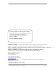
The mProm™ Module Interface (Getting Started)
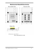
Voltage must be supplied to the mProm™ Module via pins 19 and 20 on the interface header.
The mProm™ Module regulates its voltage on board, but must be supplied a voltage between
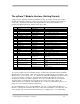
3.5-14 Volts. The table below outlines the 26 pin interface to the mProm™ Module. The
mechanical diagram that follows indicates where pin-1 starts.
Pin # Pin Name Pin Type Description
1 CNVss Digital Input
2 BUSY/UART_CS Digital I/O Pin set to function as UART
3 GDO2_CC1100 Digital I/O
4 3.3V Power (RF/Dig.) 3.3V regulated output voltage
5 CE Digital I/O Chip enable
6 DfromMicro_UART Digital Input Data sent from microprocessor
7 P_SCLK Digital I/O Programming clock
8 DfromPC_UART Digital Input Data sent from computer
9 GND SIGNAL Ground (Digital) / RF Digital ground connection
10 GPIO6 Digital I/O PWM GPIO
11 RESET Digital Input Resets the microprocessor
12 GPIO7 Digital I/O PWM GPIO
13 UART_CLK Digital I/O CLK pin for configurable UART
14 GPIO3 Digital I/O Interruptible GPIO
15 GPIO5 Digital I/O Interruptible GPIO
16 GPIO4 Digital I/O Interruptible GPIO
17 A0 Digital I/O-Analog In A/D converter
18 3.3V Power (RF/Dig.) 3.3V regulated output voltage
19 GND SIGNAL Ground (Digital) / RF Digital ground connection
20 V
unreg
3.6V Battery
Connection
3.4V-12V battery/power connection (absolute
max 14 V)
21 A1 Digital I/O-Analog In A/D converter
22 GPIO1/PROG_RxD Digital I/O Pin set to function as UART / Programming
UART
23 A2 Digital I/O-Analog In A/D converter
24 GPIO2/PROG_TxD Digital I/O Pin set to function as UART / Programming
UART
25 A3 Digital I/O-Analog In A/D converter
26 GPIO0 Digital I/O Pin set to function as UART
Once power is applied to pins 19 and 20, primary communication through the mProm™ Module
will take place on pins 6 and 8. These pins are the buffered UART interface to the Module. This
UART interface is 3.3-Volt logic only. To communicate with a PC and RS232 Translator must be
used on the customer’s end device. The mProm™ Programmer Board, used for prototype
development, translates the UART signaling to PC levels. Innovative Wireless Technologies’
document “mPros™ Network Interface Specification” (version P10 or later) outlines the
communication protocol utilized on the UART plus the over the air communication protocols for
your peer-to-peer and mesh network configurations.
Once the UART link has been correctly initialized, your device can then utilize the mProm™
Module to communicate information wirelessly to other mProm™ Modules. This allows the end
user to quickly setup communication links between two or multiple devices. If communication