
Owner Manual


5
INSTALLATION AND QUICK START UP GUIDE
Follow these instructions for quick and easy start up of your new spa. If you have any questions concerning start up,
contact your dealer or InnovaSpa (Lumi-O | Innovaplas inc) directly for help.
OUTDOOR INSTALLATION
If you are going to install your spa outdoors, select a solid, level surface to place it on. The bottom of your spa is totally protected
and it will not rot. Special preparation, such as a concrete pad or wood deck, is not mandatory, although they make very suitable
bases. If installing your spa on a wood deck, ensure that the deck is built to code and that it will withstand the filled weight of the
spa. When full, your spa weighs approximately 90 lbs (41kg) per square foot. Ensure that you do not install your spa underneath
overhead power lines.
INDOOR INSTALLATION
If you are going to install your spa indoors, you should ensure that your doorway is at least 36 inches (91 cm) wide. The location
where you intend to place your spa should be equipped with adequate ventilation, to remove chemical odors and added humidity,
and adequate drainage to handle splashing and in case of a spa leak. It is not recommended to install your spa above a ground
level floor.
INSTALLATION
1. CONNECTING THE ELECTRICITY: If you plan to operate your spa using a 110 volt electrical supply, a 12’ electrical cord, with
attached GFCI, is already connected to your spa. It must be plugged into a dedicated 15 amp wall outlet. DO NOT plug the cord
into your electrical outlet until you have completed Step 4 and your spa is full of water. DO NOT use an extension cord. If you plan to
operate your spa using a 220 volt electrical supply, you will be required to install a 220 volt GFCI breaker and disconnect box.
You will require a minimum 30 amp GFCI. It is recommended that you use a certified electrician to install your GFCI breaker
and disconnect box and to connect your spa to your house electrical panel. The spa pack in the 110-16 model is convertible
and can be connected with a 110 volt or a 220 volt electrical power supply. Instructions to convert the spa pack are located
on the inside of the spa pack cover. Ensure that the 220 volt breaker is disconnected until you have completed Step 4 and your spa
is full of water.
2. SETTING THE SPA IN PLACE: Move your new spa to the location where it will be installed. Leave a minimum of 36 inches (91 cm)
of space at each end of the spa. This ensures that you will be able to remove the end panels and you’ll be able to access
your spa equipment. Leave enough room on the side(s) of the spa to be able to take your cover off and put it back on without
obstruction.
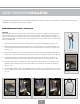
3. ATTACHING THE ACCESSORIES: Open the accessories box and remove the waterfall assembly. Lubricate the rubber O-ring with
a bit of water and insert it into its housing on the top of the spa. Remove the four fork lift channel covers and the hardware kit.
Following the instructions in the hardware kit, install the covers. Do this before you ll the spa with water. You may have to slightly
lift the spa to position the covers in their proper place.
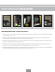
4. CHECKING THE CONNECTIONS AND SETTINGS: Remove the door at the end of the spa with the captain’s chairs. To remove the
door(s), remove the 4 screws located near the ground in each door. Check the unions to the pump and to the heater manifold
to ensure that they are tight. Vibration during shipping may cause them to loosen. Do not overtighten these unions with channel
locks. You could crack or damage them. It is also recommended that you check these unions regularly. Pump vibration can cause
them to loosen and this can cause a leak. Ensure that the two slice valves are in their open positions and that they have shaft
lock clips installed on the stems to prevent self-closing. Ensure that the shut off valve on the end of the drain hose assembly
is closed. It is located in the end with the equipment. Remove the cover of the equipment pack by loosening the two screws
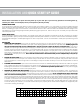
at the front. Near the bottom of the circuit board, you will see a small red panel with 10 white DIP switches. These switches
should be factory set; however, you should ensure that they are properly set as shown below. Replace the equipment pack
cover after checking the settings
MODEL
110-16 (110V) 110-16 (220V)
ON
X X X X X X X
OFF
X X X X X X X X X X X X X
DIP #
1 2 3 4 5 6 7 8 9 10 1 2 3 4 5 6 7 8 9 10