
User guide

Page 87
Genesis II Installation Instructions
© Mass Electronics Pty Ltd 2010Chapter 4 – Commissioning
Sensor #7
Innotech T emperatur e
Sensor #8
Innotech T emperatur e
Sensor #9
Innotech T emperatur e
Sensor #10
Innotech T emperatur e
Sensor #1 1
Innotech T emperatur e
Address
jumpers
Remote Expansion Module #1 (AI)
ANALOGUE INPUTS
SCREEN MUS T
GO HERE !
38 39 40 41
+
+
- -
12V PC
REM COMMS
GENESIS II DDCINNOTECH
(Wiring diagram - bottom board)
363534
33
3231302928272625242322
AI1 AI2 AI3 AI4 AI5 AI6 AI7 AI8
+
+
+
+
+
+
+
+
-------
-
2120
SCR
SS
OUTPUTS
ANALOGUE
01 02
03 04 05 06 07 08 09 10
11 12
13
14
15 16
76
75
7473
6867
66
1 32 4 9 121110
88
87
8685
8079
78
5 76 8
13 161514
84
727170
69
8382
81
Siren
SSR #3
VAV #3
VAV #4
SSR #4
SSR #1
VAV #1
VAV #2
SSR #2
SSR #5
VAV #5
Sensor #6
Innotech Temperture
Switchboard Temp
Thermistor, Philips 10k
AI LEM #1, Terminal 3
NC
Sensor #5
Innotech Temperture
Sensor #4
Innotech Temperture
Sensor #3
Innotech Temperture
Sensor #2
Innotech Temperture
Sensor #1
Innotech Temperture
TD1: 0-250 µAmps
TD1: 0-250 µAmps
TD1: 0-250 µAmps
TD1: 0-250 µAmps
TD1: 0-250 µAmps
TD1: 0-250 µAmps
AIM: <external>
TH7: Thermistor
TD1: 0-250 µAmps
TD1: 0-250 µAmps
TD1: 0-250 µAmps
TD1: 0-250 µAmps
ANALOGUE
INPUT
SIGNAL
CONDITIONERS
77
89
37
91 92 93 9490
+
C
+
-
-
Global Ne t
RS-485
RS-232
3
21
TX
RX
CIRCUIT FROM DDC OR REM
CIRCUIT TO O THER REMS
+
-
SHLD2
SHLD1
RS485(+ )
RS485(-)
RS485(-)
RS485(+ )
COMMS CONNECTIONS
24 V AC SUPPL Y
0 V AC SUPPL Y
COMM EARTH
CIRCUIT FROM DDC OR REM
+
-
SHLD2
SHLD1
RS485(+ )
RS485(-)
A
C
B
D F
E
G
H
I J
LK
SCREEN
SCREEN
+A1-
+A2- +A3- +A4- +A5- +A6-
AI2
AI1
AI4AI3 AI5 AI6
A1
A2
A3
A0
TD1: 0-250 µAmps
TD1: 0-250 µAmps
Sensor #1 1
Innotech T emperatur e
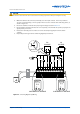
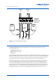
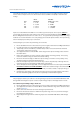
For example, an analogue input channel that has Model TH2 AISC assigned receives its input from a
thermistor device; the input circuit is checked by measuring its resistance, which should be between
0 and 2k. Procedures for checking the resistance are contained in section 4-1.2.9.
The type of AISC for each analogue input channel is determined when the system configuration is
established by the Genesis Configuration Soware prior to delivery. The configuration soware
automatically generates a Materials List and a Wiring Diagram, which are delivered with the system.
The Materials List shows the number of AISCs by type but does not show which analogue input
channels they are assigned to. The Wiring Diagram (Figure 4-5) identifies the AISC type for each
analogue input channel.
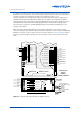
When an Analogue Input Module REM is used, the output of the REM is connected to one of the
controller’s analogue input channels. When checking the analogue connection between the GEN II AI
REM and a controller, ensure the cable is wired in accordance with the Electrical Installation chapter
and is free of potential physical damage. Ensure also that the cable is routed outside of the cable
ducts.
Figure 4-5: Analogue Input Signal Conditioner (AISC) Locations