
User guide

Page 85
Genesis II Installation Instructions
© Mass Electronics Pty Ltd 2010Chapter 4 – Commissioning
442
43
44 45
46
47 48
NO NOC
V
AC
V
DC
0V
+
-
V
AC
V
DC
240V
+
-
0V 24V
AC/DC
GENESIS II
DIGITAL
CONTROLLER
TERMINALS
EXTERNAL
DEVICE
RELAY
ON
RELAY
OFF
NO CNOC
24V
AC/DC
0V
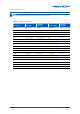
4-1.2.6 Checking Analogue Input Wiring
The analogue input wiring for the following Genesis units should be checked as part of the
commissioning process:
• GENII DDC Digital Controller
• MPCII Mid Points Controller
• GENII AI REM
Checking analogue input wiring requires special consideration due to the wide variety of analogue
input devices that may be used in the system. Some input devices function as signal voltage sources;
some devices function in the loop current mode and others provide resistive inputs to the Genesis
unit. For this reason there is no single procedure that can be used on all analogue inputs.
Procedures presented in this manual are based on identifying the type of Analogue Input Signal
Conditioner (AISC) assigned to each analogue input channel. Since each analogue input device
requires a specific AISC type to match the signal to the Genesis unit, the type of AISC assigned to
an analogue input channel indicates the type of input signal and the range. The various types of
AISCs are listed in Table 4-3 along with the type of analogue signal and the range. Reference to the
paragraph containing the instructions for checking the input wiring is also provided in Table 4-3.
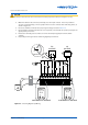
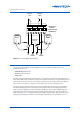
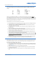
Figure 4-4: Checking Digital Output Wiring