
User guide

Page 43
Genesis II Installation Instructions
© Mass Electronics Pty Ltd 2010Chapter 3 – Electrical Installation
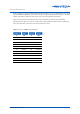
3-3.2 MPCII Mid Points Controller
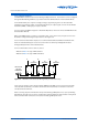
Figure 3-4 shows the input/output connection groups for the MPCII Mid Points Controller. The MPCII
Mid Points Controller uses terminal strips located around the controller’s perimeter. Terminals are
grouped by function as follows:
• Power Input (3-3.2.1)
• Digital Inputs (3-3.2.2)
• Digital Outputs (3-3.2.3)
• Analogue Inputs (3-3.2.4)
• Analogue Outputs (3-3.2.5)
• Remote Expansion Modules (REM) Connector (3-3.2.6)
• RS232 Serial Communications (Comms) Port (Network Installation)
• Net & Global Communications (Comms, RS485) Terminal (Network Installation)
RS-232 COMMS
COMMS
NET
COMMS
REM
GLOBAL
COMMS
MPC
Cobar
POWER
DIGI
TALINPUTS
SCREENS
ANALOGUE INPUTS
RS232
CONNECTOR
REM
POR
T
RS485
COMMS
ANALOGUE
OUTPUTS
DIGITAL OUTPUTS
Figure 3-4: MPCII Mid Points Controller Input / Output Terminals