
User guide

Genesis II Installation Instructions
Page 38 © Mass Electronics Pty Ltd 2010Edition 2.0 dated 06/12/2013
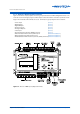
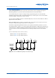
3-3.1.3 Digital Outputs
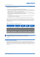
Each of the Genesis II Direct Digital Controller’s twelve digital output channels (Terminals 42–65)
consists of a single-pole, double-throw (SPDT) relay. The two terminals assigned to each channel
represent the associated relay’s Normally Open (NO) and Common (COM) contacts.
Digital output relay contacts are rated at 24VAC, 2A. Good practice is to use pilot relays for the actual
switching functions, particularly when it applies to inductive loads such as coils, solenoids and
motors. This protects the relays of the Digital Output channel and has the advantage of allowing the
pilot relays to be installed adjacent to the controlling switch-gear.
Refer to Table 3-4 for Digital Output terminal number assignments.
Normally Open (NO) Common (COM)
Terminal Signal Terminal Signal
42 DO 1 NO 43 DO 1 COM
44 DO 2 NO 45 DO 2 COM
46 DO 3 NO 47 DO 3 COM
48 DO 4 NO 49 DO 4 COM
50 DO 5 NO 51 DO 5 COM
52 DO 6 NO 53 DO 6 COM
54 DO 7 NO 55 DO 7 COM
56 DO 8 NO 57 DO 8 COM
58 DO 9 NO 59 DO 9 COM
60 DO 10 NO 61 DO 10 COM
62 DO 11 NO 63 DO 11 COM
64 DO 12 NO 65 DO 12 COM
Table 3-4: Genesis II DDC Output Signal Conditions