
User guide

Page 35
Genesis II Installation Instructions
© Mass Electronics Pty Ltd 2010Chapter 3 – Electrical Installation
3-3.1 Genesis II Direct Digital Controller
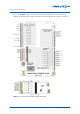
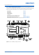
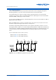
Figure 3-2 shows the input/output connection groups for the Genesis II Direct Digital Controller. The
controller uses Phoenix type plug-in terminal strips located around the controller’s perimeter. Both
single row and double row terminals are used. Terminals are grouped by function as follows:
• Power Input (3-3.1.1)
• Digital Inputs (3-3.1.2)
• Digital Outputs (3-3.1.3)
• Analogue Inputs (3-3.1.4)
• Analogue Outputs (3-3.1.5)
• Pulse Input (3-3.1.6)
• Remote Expansion Modules (REM) Connector (3-3.1.7)
• RS232 Serial Communications (Comms) Port (Network Installation)
• Optional Ethernet Communications Port (Network Installation)
• Net & Global Commmunications (Comms, RS485) Terminal (Network Installation)
Figure 3-2: Genesis II DDC Input / Output Terminals