
User guide

Page 29
Genesis II Installation Instructions
© Mass Electronics Pty Ltd 2010Chapter 2 – Mechanical Installation
2-4 Dierence Data
This paragraph contains dierence data unique to installation of the MPCII Mid Points Controller,
Genesis II System REMs and related devices. Installation instructions provided in Section 2-3 are
applicable except where stated otherwise.
2-4.1 REM Limitations
The following limitations apply to the installation of REMs:
• A Genesis II Direct Digital Controller must have Version 4 firmware or greater installed to support
REM Modules.
• For pre-version 5 controllers, a GENII RMI Remote Module Interface is required to connect REM
Modules. Refer to datasheet DS15.01 GENII RMI Remote Module Interface for more information.
• Gen2Config v4.0 or greater must be used to configure a Genesis II Direct Digital Controller that has
REM Modules connected to it.
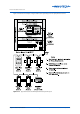
• REM units designed for DIN rail mounting should be mounted on DIN rails in cabinets approved for
switchgear or industrial control equipment, with the exception of the GENII WMI (See 2-4.2).
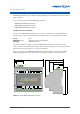
Gen2Config V4.0 or greater automatically configures the Genesis II Series digital controller, and produces a printout
which lists the types and quantities of REMs that can be used with a given Genesis II Series digital controller.
The following information provides generalised REM type/quantity requirements that can be used for planning
purposes.
NOTE
• Up to 15 REMs can be connected to a single Genesis II Direct Digital Controller or MPCII Mid Points
Controller, with one exception – the MP REMs. The MP REM can only be addressed between 1 and 8
and only 8 MP REMs can be used.
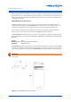
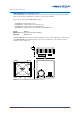
2-4.2 Installation of GENII WMI Wireless Module Interface
Follow the General Installation Guidelines (2-3.2) except:
• Do not install the GENII WMI inside a fully enclosed metal switchboard.
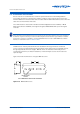
• The GENII WMI should be mounted within a 20 metre radius of all SENRx Modules from which it will
be receiving data.