
User guide

Page 21
Genesis II Installation Instructions
© Mass Electronics Pty Ltd 2010Chapter 2 – Mechanical Installation
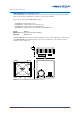
2-2.2.2 REM Control Station Modules
REM Control Station Modules are housed in a switchplate that mounts in standard electrical wall
plates at a remote location. Mechanical installation instructions for the REM Control Station Modules
are not applicable; electrical installation instructions for these modules are contained in the
Electrical Installation Chapter.
There are a total of three dierent REM Control Station Modules.
• GENII CS REM Control Station Module
• GENII CSAH REM Control Station A/H Module
• GENII CSFCAH REM Control Station Fan Control, A/H Module
Common Enclosure Information
Colour: White
Mounting: Wall Mounted
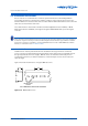
The cable run between a digital controller and GENII CS REM Control Station Modules should not
exceed 600 metres. However, the maximum cable length can be increased through the use of
Innotech Repeater IR11 module. (See Paragraph 5-3.3.3 for more information)
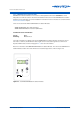
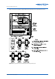
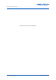
Below is a schematic of the GENII CS REM Control Station Module. The above listed REM Control
Station Modules feature the same dimensions and similar appearance. Refer to Figure 2-5.
Timer
Run
On
Off
Figure 2-5: GenII CS REM Control Station Module