
User guide


Genesis II Installation Instructions
Page 20 © Mass Electronics Pty Ltd 2010Edition 2.0 dated 06/12/2013
2-2.2.1 REM I/O Expansion Modules
REM I/O Expansion Modules increase the Input and/or Output capabilities of a Genesis II Series digital
controller.
There are a total of six dierent REM I/O Expansion Modules.
• GENII AI REM Analogue Input Module
• GENII AO REM Analogue Out Module
• GENII DI REM Dry Contact Digital Input Module
• GENII DO REM Relay Output Module
• GENII IDI REM Opto Isolated Digital Input Module
• GENII PI REM Pulse Input Module
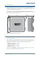
Common Enclosure Information
The above listed REM I/O Expansion Modules are housed in a rectangular case made from flame
retardant polycarbonate / ABS plastic listed under UL94. ( GENII AO REM is listed under UL94-VO)
Colour: Grey
Dimensions (max): 75mm(w) x 155mm(h) x 57mm(d)
Mounting: DIN Rail Mounted
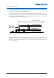
The cable run between the digital controller and the REM I/O Expansion Modules should not exceed
600 metres. However, the maximum cable length can be increased through the use of Innotech
Repeater IR11 module. (See 5-3.3.3 for more information)
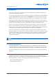
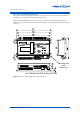
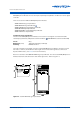
Below is a schematic of the GENII AI REM Analogue Input Module. The above listed REM I/O Expansion
Modules feature the same dimensions and similar appearance. Refer to Figure 2-4.
75
57
155
GENESI S
ANALOG INPUT
Re mote ExpansionModule
123
TX
RX
A CB DFE G H IJ LK
SCREEN
SCREEN
+A1- +A2- +A3- +A4- +A5- +A6-
Figure 2-4: GenII AI REM Analogue Input Module