Operation Manual Pathfinder Matrix Switcher Series IN50000 Composite / S-Video Switchers IN60000 RGBS Switchers ®
Installation and Safety Instructions For Models without a Power Switch: The socket outlet shall be installed near the equipment and shall be accessible. For Models with 110 / 220V Power Selector: Caution: Before applying power to this unit, the voltage selector must be set to the appropriate setting to match local A/C line voltage. Improper setting of the voltage selector may cause damage to the unit and create a potential fire hazard.
Installations und Sicherheitshinweise Für Geräte ohne Netzschalter: Die Netzsteckdose soll in de Nähe des Gerätes installiert und frei zugänglich sein. Für Geräte mit 110 / 220V Spannungswähler: Achtung: Bevor Sie dem Gerät Spann ung zuführen, muß der Spannungswähler entsprechend der Spannung des lokalen Wechselspannungsnetzes eingestellt werden. Die falsche Stellung des Spannungswählers kann eine Beschädigung des Gerätes und möglicherweise ein Feuer verursachen.
CE COMPLIANCE All products exported to Europe by Inline, Inc. after January 1, 1997 have been tested and found to comply with EU Council Directive 89/336/EEC. These devices conform to the following standards: EN50081-1 (1991), EN55022 (1987) EN50082-1 (1992 and 1994), EN60950-92 Shielded interconnect cables must be employed with this equipment to ensure compliance with the pertinent Electromagnetic Interference (EMI) and Electromagnetic Compatibility (EMC) standards governing this device.
TABLE OF CONTENTS Product Overview...................................................................................................................................... 1 Description........................................................................................................................................ 1 Fixed Configuration vs. Reconfigurable Switchers........................................................................... 1 Model Numbers ...................................................
1 PRODUCT OVERVIEW Description: The PATHFINDER series switchers are designed to route multiple RGB and audio signals to multiple output devices. A typical installation may involve computers, monitors, large screen data projectors, VCR’s and video cameras. PATHFINDER series switchers are commonly installed in board rooms, training centers, monitoring facilities, simulation systems and any other installation requiring comprehensive routing over multiple video and audio sources.
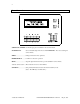
2 FRONT PANEL CONTROLS SCROLL UP & DOWN: Scrolls through options available in various menu levels. SAVE/RECALL: Saves or Recalls setup memories of the PATHFINDER. Also saves setti9ngs for various menus. MENU: ............................ Changes menus and exits operations. ENTER/SELECT: .......... Confirms or selects an operation. NEXT:.............................. Steps through menu items and/or options available in various menus. 1, 2, 3, 4, 5, 6, 7, 8, 9, 0: ..
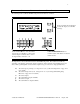
3 SWITCHING - CONNECTING INPUTS AND OUTPUTS (FRONT PANEL) The switching menu is called the PATH Config menu, and it functions as follows: Use the Up and Down Scroll button to select the output you would like to change. Use the number buttons to enter the number of the input you would like to connect to the selected output. It is always best to enter a two digit number, such as 03 or 12. Use the ENTER/SELECT button to confirm a switch. This button executes the switch selected.
4 Step 1: Select the Output: To make a connection between an input and an output, you scroll through each available output and then assign it an input. This may seem backwards at first, but when you think about it more carefully, you will see that it is not. A routing matrix switcher can have one input going to several outputs simultaneously, but an output can only have one input (unless you want to see multiple image on top of each other).
5 SAVING AND RECALLING SETUP MEMORIES The PATHFINDER can store and recall up to 8 setup memories. A memory stores input to output connection information, and when recalled, executes all of the switch connections. When the PATHFINDER is turned on, it uses setup #1 as the default, and this cannot be changed. If you plan on turning off the PATHFINDER, make certain to store the initial settings in Setup #1.
6 Recalling a Setup Memory: To recall a memory configuration, push the SAVE/RECALL button. One of two screens will appear depending on whether you made any input to output connection changes. No Changes Made: If no changes were made, the unit will prompt you to select a memory setup as follows: The unit shows you the current setup #b, with a blinking cursor over the number. The blinking cursor indicates that you can change this by using the number buttons to enter the desired setup#.
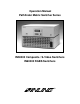
7 PATH Mapping: The PATH Mapping section gives you visual feedback of how the PATHFINDER is configured, that is which inputs are connected to which outputs. Enter this sections by pressing the ENTER/SELECT button when the screen reads as follows: The following screen will appear (although it will appear different for your unit): A blank square designates no input (i.e.: The output is blank) The number on top of the output designates the input connected to that output.
8 Group Mapping: The GROUP Mapping section gives you visual feedback of which boards are in which group (see Board Configuration on page 13 for more details). Enter this section by pressing the ENTER/SELECT button when the screen reads as follows: The following screen will appear (although it may appear different for your unit): The number on top of the board designates the group that board is in.
9 RGB Delay: RGB Delay is a key feature of the PATHFINDER. It provides an adjustable delay time (0 to 6 seconds) between switching the sync and RGB boards. The sync signal is connected first and the RGB signals are blanked while the display device is allowed to lock up to the new signal. RGB delay prevents the display device from showing re-sizing and other spurious on-screen effects which often occur while the display is adjusting to the new signal.
10 LCD Contrast Adjust: The LCD Contrast Adj. section allows you to adjust the contrast of the PATHFINDER’s front panel LCD screen. Press the ENTER/SELECT button when the screen reads as follows: The following screen will appear: The UP Scroll button will increase the contrast while the DOWN Scroll button will decrease the contrast.
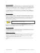
11 The following screen will appear (although it may appear different for your unit if it is already set for a baud rate other than 1200): The asterisk, *, in the bottom right hand corner of the display indicates that this baud rate is currently selected. To view the other rates available, press the NEXT button, and the baud rate will change to the next highest rate, which would be 2400bps for this example.
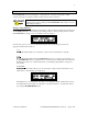
12 The following screen will appear (although it may appear different for your unit if it is already set for a different Command Code): The asterisk in 1[]* indicates that this Command Code is currently selected,. To choose a different Command Code, press the corresponding number button. For example, pressing the number 3 button will place the asterisk in 3()*, choosing the parenthesis as the Command Code.
13 C/N# Model # Description 06140101 IN60016 16 Port Reconfigurable Switcher 06001204 IN61204 12 in, 4 out Fixed Switcher 06000808 IN60808 8 in, 8 out Fixed Switcher Press any button to exit this section. POWER-ON ADJUSTMENTS The PATHFINDER utilizes Power-On adjustments to access critical parameters of the unit.
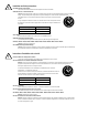
14 Enter this section by pressing the ENTER/SELECT button. The following screen will appear (although it may be different for your unit): The screen above shows the boards currently assigned to Group 1.
15 Enter this section by pressing the ENTER/SELECT button. The following screen will appear (although it may be different for your unit): G1 indicates you are setting the I/O configuration for Group 1. The current setting is 1 active output out of a possible 4 outputs.
16 USING RS-232 CONTROL The PATHFINDER has two 9 pin RS-232 ports which will accept serial commands from a control system, computer serial port, or any other device capable of sending out serial ASCII commands at compatible baud rates. All switching, configuration and set-up parameters can be controlled using RS-232 commands.
17 Controlling Multiple INLINE Products: Many INLINE products such as the PATHFINDER, the IN1222/IN1240/IN1422 scan doublers and the IN1510/IN1540/IN1710 decoders use similar communication protocol structures. By setting each unit to a different Command Code, up to four INLINE products can be controlled independently by a single RS-232 serial control port (Note: A RS-232 distribution amplifier may be required.) RS-232 Port Pin-outs: There are two RS-232 ports on the PATHFINDER.
18 COMMAND1 ACI3 * ACI4 * ACI5 * ACI6 * ACI7 * CALLs SAVEs SAVE0 PTgOmmInn Lgo1o2o3 . . . SW RGBx.x GgBb1b2b3 . . . IOgOoIi FP FP0 * * COMMAND1 1 * DESCRIPTION Set to 1200 baud rate, default setting Set to 2400 baud rate Set to 4800 baud rate Set to 9600 baud rate Set to 19200 baud rate Recall configuration from SETUPs s: 1 byte ASCII code, ranges from 1 - 8 Save current configuration to SETUPs s: 1 byte ASCII code, ranges from 1 - 8 Save Global setting(s) Execute a switch.
19 FP1 * FP2 * INF0 INF1 1 * Enable the front panel operation (take the unit out of the Stand-by mode and Executive mode). Executive mode. Disable access to configuration menus from the front panel (Path Config, RGB delay, RS-232 baud rate, and Command code). Get the firmware version Get the Configuration Number (C/N). [OK] [OK] [PATHFINDER V2.0a] Varies with model # Leading and ending codes not shown for clarity.
20 WARRANTY ♦ INLINE warrants the equipment it manufactures to be free from defects in materials and workmanship. ♦ If equipment fails because of such defects and INLINE is notified within two (2) years from the date of shipment, INLINE will, at its option, repair or replace the equipment at its plant, provided that the equipment has not been subjected to mechanical, electrical, or other abuse or modifications.