
Installation Manual
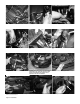

Install the upper intake tube assembly with straight
hose and clamps provided and connect the 2 tubes
together.
Re-install the bumper cover. Make sure everything is tighten. Position for
best possible fit. For Short ram, remove the lower intake assembly and
attach the filter to the upper intake tube assembly and secure. Note: Short
ram is temporary or for Extreme Weather conditions only, vehicles Max
Performance will perform in Cold air configuration only. Vehicle in
Short ram only may cause for a change in fuel trims, resulting in
possible Check Engine Light.
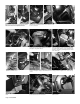
Position the intake for the best fit and tighten the
vibra mount using the remaining washer and nut and
tighten using 10mm socket or wrench.
Position the intake for the best fit and tighten all
clamps on intake usign 8mm nut driver
Figure 27
Figure 29
Figure 28
Figure 33
Page 4 of Part# SP7029
0< a%(.#&(K%)1/,(.#(<#/51#,.A/+))+/,(.O#-1&(..1&/#/51#.1B+/,J1#9+//1-;#/1-K,.+)#91<(-1#;(3#A/+-/#/51#1.B,.1'##
.< T),B.#/51#1./,-1#,./+01#A;A/1K#<(-#/51#91A/#%(AA,9)1#<,/'##[.&1#/51#,./+01#5+A#911.#%-(%1-);#<,//1*#&(./,.31
/(#/,B5/1.#+))#.3/AO#9()/A#+.*#&)+K%A'
2< E1-,(*,&+));O#-1&51&0#/51#+),B.K1./#(<#/51#,./+01#A;A/1K#+.*#K+01#A3-1#/51-1#,A#%-(%1-#&)1+-+.&1#+-(3.*
+.*#+)(.B#/51#)1.B/5#(<#/51#,./+01'# #b+,)3-1#/(#<())(4#%-(%1-#K+,.1./+.&1#%-(&1*3-1A#K+;#&+3A1
*+K+B1#/(#/51#,./+01#+.*#4,))#J(,*# /51#4+--+./;'
=< ]/+-/#/51#1.B,.1#+.*#),A/1.#&+-1<3));#<(-#+.;#(**#.(,A1AO#-+//)1A#+.*:(-#+,-#)1+0A#%-,(-#/(#/+0,.B#,/#<(-#+#/1A/
*-,J1'##W<#+.;#%-(9)1KA#+-,A1#B(# 9+&0#+.*#&51&0#/51#J+&33K#),.1AO#5(A1A#+.*#&)+K%A#/5+/#K+;91#&+3A,.B
)1+0A#(-#-+//)1A#+.*#&(--1&/#/51#%-(9)1K'
U< `51&0#/51#<,)/1-#<(-#1c&1AA,J1#*,-/#93,)*#3%'##`)1+.#(-#-1%)+&1#/51#<,)/1-#4,/5#+.#(-,B,.+)#W.X1.#<,)/1-#=&+.#91#
9(3B5/#(."),.1#+/#d,.X1.(.),.1'&(K8@'##`(.B-+/3)+/,(.Ae## f(3#5+J1#X3A/#&(K%)1/1*#/51#,.A/+))+/,(.#(<#/51#91A/##
,./+01#A;A/1K#A()*#(.#/51#K+-01/'## ##\.X(;#/51#+**1*#%(41-#+.*#%1-<(-K+.&1#(<#;(3-#.14#,./+01#A;A/1K'
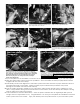
Congratulations! You have just completed the installation of this intake system.
Periodically, check the alignment of the intake, normal wear and tear can cause
nuts and bolts to come loose.
Note: Check clearance and adjust if needed!
Failure to check the alignment and adjust the intake can cause damage that
will void the warranty. Injen Technology is not responsible for any damages
caused by/from improper installation.
Figure 34
Re-connect the MAF sensor harness.
If you want, you can remove the drain plug from
the vehicle’s frame. This will not plug into the
new intake system.
Re-install the air box snorkel and secure the bottom
end of snorkel with provided zip ties to prevent from
moving.
Figure 30
Figure 32
Figure 31
Cold air shown
Short ram shown
(Temporary)