
System Manual


Connector Assignments
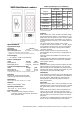
Wiegand / Clock and Data / TTL serial
500-5005 INID MultiSmart reader WG/C&D/TTL
500-5045 INID MultiSmart PIN reader WG/C&D/TTL
1 LED 1 - Green 5 BUZZER RXD
2 LED 2 - Amber 6 TAMPER
3 D1 DATA TXD 7 GND
4 D0 CLOCK TXE 8 POWER
RS485 / RS422
500-5015 INID MultiSmart reader RS485/RS422
500-5055 INID MultiSmart PIN reader RS485/RS422
1 LED 1 - Green 5 RS485 n.c. RS422 RX-
2 LED 2 - Amber 6 RS485 n.c. RS422 RX+
3 RS485 TRX+ RS422 TX+ 7 GND
4 RS485 TRX- RS422 TX- 8 POWER
Caution:
floating communication lines may cause spurious emissions.
Ensure all communication lines are properly biased and terminated.
RS232
500-5025 INID MultiSmart reader RS232
500-5065 INID MultiSmart PIN reader RS232
1 LED 1 - Green 5 RTS
2 LED 2 - Amber 6 RXD
3 CTS 7 GND
4 TXD 8 POWER
CAN bus
500-5035 INID MultiSmart reader CAN bus
500-5075 INID MultiSmart PIN reader CAN bus
1 LED 1 - Green 5 n.c.
2 LED 2 - Amber 6 n.c.
3 CANL 7 GND
4 CANH 8 POWER
Parts list
1 Reader front qty: 1
2 Terminal connector qty: 1
3 Mounting backplate qty: 1
4 Enclosure screw qty: 1
5 Installation sheet qty: 1
Installation instructions
1 Determine an appropriate position for the reader
and drill two holes for mounting the backplate
and one hole for the cable, see diagram for
measurements. Do not mount readers less than
20 cm (8 inches) apart.
2 Pull the cable trough the hole in the backplate
and mount the backplate. Protect the cable
against sharp edges and any damage from
chafing.
3 Remove the terminal connector from the front of
the reader. Prepare the end of the cable and
wires, eliminate any loose or frayed strands. Keep
the wire ends as short as practical.
4 Connect the wires to the connector according to
the reader type. Wire ends, termination resistor
leads and optional permanent links shall be kept
as short as possible.
5 Place the connector on the reader pins.
6 Place the reader front over the hinge of the
backplate and close the reader (see diagram),
keeping the wiring in the lower part of the reader
housing. DO NOT use excessive force, retract the
cable if necessary.
7 Test the reader: apply power and present a valid
card. The LED bar should flash and the sounder
should produce a short tone indicating a
successful read. If the Host system is connected
to LED bar and sounder inputs these should
follow the functionality of the Host system.
8 The reader front should now be secured to the
backplate using the supplied enclosure screw.
This device contains 2 transmitters
Certifications
CE, FCC
FCC ID: YAB-ISOACRDR (model 50XX) 13.56 MHz
YAB-NGRPAOLF (model 40XX) 115 – 148 kHz
Compliance statement
This device complies with part 15 of the FCC Rules.
Operation is subject to the following two conditions:
1) this device may not cause harmful interference, and
2) this device must accept any interference received,
including interference that may cause undesired
operation.
Warning (part 15.21)
Changes or modifications not expressly approved by the
party responsible for compliance could void the user’s
authority to operate the equipment.
This in particular is applicable for the antenna which has
been delivered with the reader.
Consult your National Authority if any authorization
is needed for this product.
INID MultiSmart readers - installation and operation manual version 1.02; March 16, 2012
INID BV
Mariëttahof 27
2033 WS Haarlem
The Netherlands
Phone: +31 (0)23 5335 420
Web: www.inid-readers.com
For mounting, use only flat head screws with a
maximum shank size of 4 mm (5/32”, #7)