
System Manual
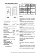


INID MultiSmart readers
Specifications
Typical read range
Technology distance
Mifare ISO card
1)
60 mm 2.4 inch
LF Proximity ISO card
2)
30 – 60 mm 1.2 – 2.4 inch
1)
Depends on transponder antenna geometry.
1)
Depends on LF technology and card antenna geometry.
Power Supply
7 - 24 Volt DC (12 VDC recommended)
Power consumption
model average peak
INID MultiSmart 1300 mW 1750 mW
INID MultiSmart PIN 1300 mW 2050 mW
Current consumption @12 VDC
3)
model average peak
INID MultiSmart 110 mA 146 mA
INID MultiSmart PIN 110 mA 171 mA
3)
Use Ohm's law to calculate current at different voltages.
Interface
Inputs type and protection specifics
Outputs type and protection specifics
Dimensions
143 x 50 x 25 mm / 5.63 x 2 x 1 inch
Material
UL94-V0 rated LEXAN
®
925U
Operating temperature
-25° to 65° C / -15° to 150° F
Protection class
IP54 Complete protection against contact,
protection against dust deposit. Protection
from splashed water.
Cable specifications (non-shielded)
interface
maximum
cable length
min.conductor size
with 12 V supply
2)
meters feet mm
2
AWG
Wiegand
61 200
0.25 24
91 300
152 500 0.34 22
Clock/Data 25 80
0.25 24
TTL serial 1.5 5
RS232 2.4 8
RS485/RS422
(cable power)
61 200
152 500 0.34 22
RS485/RS422
(local power)
1220 4000 0.25 24
CAN bus system / speed dependent
2)
With a 24V supply, minimum conductor size is AWG 24 for all
interfaces and lengths.
Features
INID readers have a slim mullion mountable design
and are designed for both in- and outdoor use. The
INID reader can be mounted on any surface without
significant performance degradation. For mounting
to a metal surface however, a non-metallic spacer is
advised.
The switch mode power supply of the reader
accepts a wide range input from 7 - 24 VDC. Higher
input voltages result in lower current consumption
and allow for cost effective wiring with a smaller
conductor diameter.
Reader output formats are determined by the
personalization of the card and/or configuration of
the reader.
Separate models are available for card-only and
card+PIN.
Electrical interface options for WG/C&D/TTL serial,
RS485/RS422, RS232 and CAN bus are available
with separate models.
PIN code
INID PIN readers provide extensive options for PIN
data formats and output protocols. The card and
PIN code data is sent separately and independently
allowing host system determined operation for card-
only, PIN-only and card and PIN usage.
Indications
User feedback is provided by a single LED bar and a
multi-tone sounder. User feedback is controllable by
the host system. PIN models are equipped with
back lighting of the PIN code digits for usage in
dark environments.
Operation
When a proximity card is read successfully the card
associated code is send to the Host system, the LED
bar lights briefly and the sounder sounds a short
tone.
When a PIN is entered the data is transmitted; at
each key press a click sound is produced and the
LED bar lights briefly. The back light of the PIN code
lights up after a successful card read or at the first
key press.
The LED bar or individual LED bar segments and the
buzzer are also controllable by the Host system.
INID MultiSmart readers - installation and operation manual version 1.02; March 16, 2012