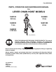
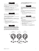
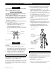
Form MHD56109 PARTS, OPERATION AND MAINTENANCE MANUAL for LEVER CHAIN HOIST MODELS SLB150 3/4 ton SLB600 3 ton LOA D FREE SLB200 1 ton SLB1200 6 ton SLB300 1-1/2 ton (Dwg. MHP0829) READ THIS MANUAL BEFORE USING THESE PRODUCTS. This manual contains important safety, installation, operation and maintenance information. Make this manual available to all persons responsible for the installation, operation and maintenance of these products.
SAFETY INFORMATION This manual provides important information for all personnel involved with the safe installation, operation and proper maintenance of this product. Even if you feel you are familiar with this or similar equipment, you should read this manual before operating the product. Danger, Warning, Caution and Notice Throughout this manual there are steps and procedures which, if not followed, may result in a hazard. The following signal words are used to identify the level of potential hazard.
SAFE OPERATING INSTRUCTIONS The following warnings and operating instructions have been adapted in part from American National Standard ASME B30.21 and are intended to avoid unsafe operating practices which might lead to injury or property damage. Ingersoll Rand recognizes that most companies who use hoists have a safety program in force in their plants.
Specifications Table Model No. Capacity (metric tons) Lever Pull to lift rated load (kg) SLB150 SLB200 SLB300 SLB600 SLB1200 3/4 1 1-1/2 3 6 18.5 27 24 24 26 Load Chain size (mm) Wt. of chain per 0.3 m of lift (kg) 6 x 18 0.24 7.1 x 21.2 No. of chain falls 7.03 1 0.34 1.66 1.32 10 x 30 Hoist Net Weight with standard 1.5 m of lift (kg) 11.0 20.0 30.4 2 INSTALLATION Prior to installing hoist, carefully inspect it for possible shipping damage.
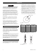
Lowering Load (DOWN Position - Payout) CAUTION Refer to Dwg. MHP0825 on page 5. • Ensure load is properly seated in saddle of bottom hook. In NEUTRAL “N” position hand lever does not engage ratchet gear. The hand lever free-wheels until selector lever is shifted to UP or DOWN position. 1. Set selector lever to NEUTRAL (center) position. 2. Turn free chain knob counterclockwise. 3. Grasp and pull one side of load chain or turn free knob until desired hook location is achieved. 4. Connect hook to load.
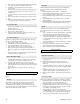
INSPECTION WARNING 1. • All new, altered or modified equipment should be inspected and tested by personnel trained in safety, operation and maintenance of this equipment to ensure safe operation at rated specifications before placing equipment in service. 2. Frequent and periodic inspections should be performed on equipment in regular service. Frequent inspections are visual examinations performed by operators or service personnel and include observations made during routine equipment operation.
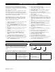
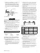
4. CHAIN. Refer to Dwg. MHP0102 on page 7. Examine each link for bending, cracks in weld areas or shoulders, transverse nicks and gouges, weld splatter, corrosion pits, striation (minute parallel lines) and chain wear, including bearing surfaces between chain links. Replace a chain that fails any of the inspections. Check lubrication and lubricate if necessary. Refer to “Load Chain” in “LUBRICATION” section. 3. 4. 5. Welded Area Diameter Wear in these areas 6. 7. 8. (Dwg.
LUBRICATION General Load Chain Thread lubricant or an anti-seize compound use is recommended for threaded shafts, capscrews and nuts. Unless otherwise stated, remove old lubricant, clean part with an acid free solvent and apply a new coating of lubricant to part before assembly. Gear Remove prevailing torque type nut (60) on side of hoist opposite hand lever and remove gear case assembly (1). Remove old grease and replace with new. For temperatures -29° to 10° C use EP 1 grease or equivalent.
MAINTENANCE WARNING • Never perform maintenance on hoist while it is supporting a load. • Before performing maintenance, tag hoist: WARNING - DO NOT OPERATE EQUIPMENT BEING REPAIRED. • Only allow personnel trained in the operation and service of this product to perform maintenance. • After performing any maintenance on hoist, test to 125% of its rated capacity before returning to service.
5. Remove change over pawl (22), spring shaft (23) and change over spring (24) from lever handle assembly (25). 6. Carefully pry change hand wheel (28) from change over gear (20). 7. Remove screw (64), washers (65) and prevailing torque type nut (60) from threaded spacers (94). Remove brake cover assembly (19). 8. Secure drive shaft (3) to prevent rotation and unscrew disk hub (15). 9. Remove friction disk (17), ratchet disk (18) and free spring (16). 10.
Brake End Assembly Bottom Hook Assembly Follow steps 1 through 6 described in ‘Load Sheave Assembly’ and steps 1 through 5 described in ‘Gear End Assembly’. 1. 2. CAUTION 3. • The brake will not operate properly if there is oil or grease on brake friction disk (17). 4. 5. 1. 6. Thread disk hub (15) onto drive shaft (3) until snug. Stepped side of brake hub must face out. 2. Install pawl springs (13) and pawls (14) to posts on side plate assembly B (brake end) (12) and secure with snap rings (63).
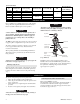
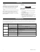
30 29 12 70 69 67 27 31 71 68 26 28 44 66 64 65 25 21 20 60 24 23 22 19 65 64 16 17 17 18 63 15 14 13 47 75 46 12 76 52 55 7 51 91 8 48 6 77 5 75 46 49 4 76 47 48 Item 45 99 54 94 45 62 60 11 2 84 51 9 93 95 10 3 1 60 96 56 97 32 75 57 67 47 46 76 82 6 ton Hoist HOIST ASSEMBLY PARTS DRAWING (Dwg.
HOIST ASSEMBLY PARTS LIST No. Description 0. 75t 1t 1.
No. Description 0. 75t 1t 1.
PARTS ORDERING INFORMATION The use of other than genuine Ingersoll Rand replacement parts may adversely affect safe operation of this product. For prompt service and genuine Ingersoll Rand parts, provide your nearest distributor with the following: 1. Complete model number and lot number as it appears on nameplate. 2. Part number(s) and part description as shown in this manual. 3. Quantity required. Capacity and lot number nameplate for SLB Hoists is located on hand lever, under selector lever.
71480545 Form: MHD56109 Edition 8 August, 2008 NOTES Declaration Of Conformity (FR) CERTIFICAT DE CONFORMITÉ (DE) KONFORMITÄTSERKLÄRUNG (IT) DICHIARAZIONE DI CONFORMITÀ (ES) DECLARACIÓN DE CONFORMIDAD (NL) CONFORMITEITSVERKLARING (DA) FABRIKATIONSERKLÆRING (SV) FÖRSÄKRAN OM ÖVERENSSTÄMMELSE (NO) KONFORMITETSERKLÆRING (FI) VAKUUTUS NORMIEN TÄYTTÄMISESTÄ Supplier's Name: Ingersoll Rand Address: Swan Lane, Hindley Green, Wigan WN2 4EZ (FR) nom du fournisseur (DE)Name des Herstellers (IT ) nome del fornito
NOTES MHD56109 - Edition 8 17
NOTES 18 MHD56109 - Edition 8
WARRANTY HOIST LIMITED WARRANTY Ingersoll Rand Company warrants to the original user its Hoists and Winches (Products) to be free of defects in material and workmanship for a period of one year from the date of purchase. Ingersoll Rand will repair, without cost, any Product found to be defective, including parts and labor charges, or at its option, will replace such Products or refund the purchase price less a reasonable allowance for depreciation, in exchange for the Product.
www.irtools.