
Product Manual

Footer 33
33
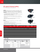
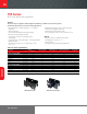
Electric Chain
Hoists
ingersollrandproducts.com/liing
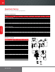
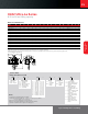
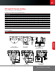
Example: QCH100-2NS200M1-21-17B4C
QCH100-2NS200 M1 21 17 B C4– –
Base model
3 phase single speed
QCH50-1NS12
QCH50-1NS25
QCH50-1NS50
QCH50-2NS100
QCH100-1NS100
QCH100-2NS200
QCH300-1NS200
QCH200-2NS300
QCH300-2NS400
QCH500-2NS500
3 phase dual-speed
QCH50-1ND12
QCH50-1ND25
QCH50-1HD25
QCH50-1ND50
QCH50-2ND100
QCH100-1ND100
QCH100-2ND200
QCH300-1ND200
QCH200-2ND300
QCH300-2ND400
QCH500-2ND500
Li (feet)
10 = Standard
15 = Standard
20 = Standard
XX = Specify
length
Pendent
drop (feet)
6 = Standard
11 = Standard
16 = Standard
XX = Specify
length
Flange width
(See catalog for
specifications)
- = Eye bolt
or hook
mount
A = See flange
width chart
B = See flange
width chart
C = See flange
width chart
D = See flange
width chart
Options
B = Trolley brake
C = Chain container
E = External strain relief
F = XX, specify power cord
length (standard is 15
on E, H, and P, and 3
on M1-M4 suspensions)
H = Handy Handle
(QCH50 single fall only)
K = 110 volt control (3
phase models only)
P = Pendent with vertical
aligned buttons
P2 = Pendent with 2 extra
vertical aligned buttons
P4 = Pendent with 4 extra
vertical aligned buttons
Y = Bullard top hook
Z = Bullard bottom hook
Voltage
3 = 230/3/60
4 = 460/4/60
5 = 575/3/60
6 =
380/3/50*
(* = these units
have extended
lead times and
are not UL or
C-UL (Canadian
UL) listed)
HOW TO ORDER
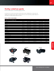
Suspension type
E = Eye bolt
H = Hook
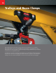
P = Plain trolley (“PT”
Series)
M1 = Motorized trolley
(normal speed 48
fpm)
M2 = Motorized trolley
(normal/dual
speed 48/16
fpm)
M4 = Motorized trolley
(high/dual speed
96/24 fpm)
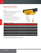
Quantum Series
0.125 to 5 metric ton liing capacities