INSTALLATION USE & CARE MANUAL ALL WEATHER W-SERIES QUARTZ TUBE ELECTRIC INFRARED RADIANT HEATER TABLE OF CONTENTS IMPORTANT INFORMATION Warnings 2 Assembly Instructions 3 Wiring Instructions 3 Outdoor Installation 3 APPLICATION INFORMATION Mounting Instructions 3-4 Typical Wiring (Schematics) 5 General Notes 5 Areas Covered (Table) 5-6 Location Suggestions 7 PARTS LIST Replacement Parts List 6 Trouble Shooting Guide 6-7 Warranty 8 SAVE THIS MANUAL FOR FUTURE REFERENCE
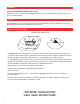
WARNINGS READ ALL INSTRUCTIONS BEFORE USING HEATER Unit may be a source of possible shock. NEVER attempt to service heater without disconnecting its power source. Source of possible ignition. CAUTION High Temperature, risk of fire, keep electrical cords, drapery, furnishings and other combustibles at least 3 feet (0.9m) from the front of heater and away from sides and rear.
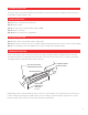
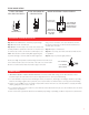
WIRING INSTRUCTIONS Step 1: Remove cover plate from junction box. Step 2: Attach conduit. Step 3: Use only copper or aluminum wire suitable for 90°C. Step 4: Replace cover plate. Step 5: Observe local electrical code regulations. OUTDOOR INSTALLATION Step 1: Heater must be mounted with reflector angled down. Step 2: All electrical connections must be in compliance with the National Electric Code and local codes for outdoor wiring.
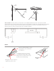
NT OI 6" MOU TO REA WALL OR CEILING SWIVEL MOUNTING BRACKETS (PAIR) CEILING WALL INSULATED HOUSING 8" WIDE 60º MAX. AI 3” M PO T IN LENGTH VARIES DEPENDING ON MODEL (MAX. 61-1/4") 60º MAX. NOTE: DO NOT mount the heater on a vertical axis. Such installation will reduce the life of the element and will CEILING automatically void the product’s warranty. Heater must be installed with the quartz tube horizontally level.
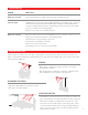
TYPICAL WIRING OPTIONS TYPICAL 120V WIRING FOR A SINGLE POLE SWITCH TYPICAL 240V WIRING FOR A TWO POLE SWITCH WIRING FOR OPTIONAL 120V/240V CONTROLS 240 V. 115 V. OFF 240 V. FOR 115V. PILOT LIGHT IF USED OFF TOP P HEATING ELEMENT L1 H1 ON BLACK WHITE ON REAR VIEW OF CONTROLLER FOR MAX. 15 AMF LOAD ONLY HEATER L2 H2 "TOP" MARKED ON REAR OF CONTROL MUST BE INSTALLED IN AN UP POSITION HEATER REPLACEMENT ELEMENT INSTALLATION Step 1: Check UL/CE label on heater for proper voltage.
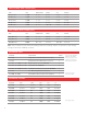
SINGLE ELEMENT AREAS COVERED (FEET) MODEL WATTS MOUNTING HEIGHT AVERAGE COLD PROTECTED W 1512 SS 1,500 6' – 8' 5' x 5' 3' x 3' 7' x 7' W 2024 SS 2,000 7' – 9' 6' x 6' 4' x 4' 8' x 8' W 2524 SS 2,500 7' – 9' 7' x 7' 5' x 5' 9' x 9' W 3024 SS 3,000 7' – 9' 8' x 8' 6' x 6' 10' x 10' W 4024 SS 4,000 8' – 11' 10' x 10' 8' x 8' 12' x 12' DUAL ELEMENT AREAS COVERED (FEET) MODEL WATTS MOUNTING HEIGHT AVERAGE COLD PROTECTED WD 4024 SS 4,000 8' – 12' 10' x 8' 8' x 6' 12'
TROUBLESHOOTING PROBLEM WHAT TO DO Heater does not glow Check supply voltage to confirm it matches voltage of heating element. Low heat output A 240 V element connected to 110 V or 208 V will warm, but not glow orange, or generate sufficient heat for typical applications. (Matching your Voltage is extremely important). If element is visibly orange, but there is insufficient heat, refer to the areas covered, with respect to conditions and mounting heights.
LIMITED PRODUCT WARRANTY Model #: Serial #: Date of Purchase: Purchased From: Thank you very much for purchasing a INFRATECH Quartz Tube Electric Heater. We have designed this heater to provide you and your family with many years of great outdoor experiences. Please fill in the Model and Serial number as well as date of purchase in the areas indicated above. Please save this information for future reference.