
Installation Manual
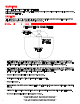
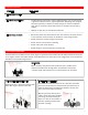

GREEN GROUND
WIRE SCREW
Connect power with flexible
conduit or appropriate cord
to allow heater to be swiveled.
The Junction Box inlet hole is
sized for a standard ½” weather
tight conduit fitting and has a
locknut located on the inside of
the box for fastening.
Junction Box on top of the heater
has a gasket side access cover
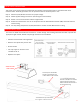
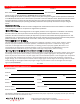
This heater must be permanently installed and hard wired by a licensed electrician in accordance with local
electrical codes. Assembly procedure must be performed with no electrical power to unit.
Step 1: Check UL/CUL/CE label on heater for proper voltage.
Step 2: Follow supplied wiring instructions. (See wiring instructions below)
Step 3: Heater must be mounted with reflector angled down.
Step 4: All electrical connections must be in compliance with the National Electric Code (NEC) and local codes for
outdoor wiring.
Step 5: Use only wiring components UL/CUL/CE listed for outdoor use with IPX4 minimum rating.
INSTALLATION INSTRUCTIONS
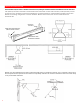
WIRING INSTRUCTIONS
The heater is drilled and threaded for standard ½” conduit fittings. The installing electrician will need to provide the
appropriate rigid metallic, flexible or liquid tight conduit for the installation.
• Observe local electrical code regulations.
• Remove cover plate from junction box.
• Attach conduit.
• Use only copper or aluminum wire
suitable for 90°C.
• Replace cover plate.
3
has a gasket
T