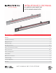
INSTALLATION USE & CARE MANUAL ALL WEATHER SL-SERIES QUARTZ TUBE ELECTRIC INFRARED RADIANT HEATER TABLE OF CONTENTS Warnings 2 Installation Instructions 3 Wiring Instructions 3 Bracket Spacing 4 Mounting Instructions 4-5 Replacement Element Installation Replacement Parts 5 5-6 Heater Coverage Areas 6 General Notes 6 Maintenance Instructions 6 Trouble Shooting 7 Location Suggestions 7 Warranty 8 SAVE THIS MANUAL FOR FUTURE REFERENCE
WARNINGS READ ALL INSTRUCTIONS BEFORE USING HEATER. Unit may be a source of possible shock. NEVER attempt to service heater without disconnecting its power source. Source of possible ignition. WARNING: If not installed, operated and maintained in accordance with the manufacturer’s instructions, this product can expose you to chemicals including nickel, which are known to the State of California to cause cancer. For more information go to www.P65Warnings.ca.gov.
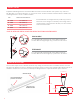
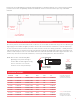
INSTALLATION INSTRUCTIONS This heater must be permanently installed and hard wired by a licensed electrician in accordance with local electrical codes. Assembly procedure must be performed with no electrical power to unit. Step 1: Check UL/CUL/CE label on heater for proper voltage. Step 2: Follow supplied wiring instructions (see wiring instructions below). Step 3: Heater must be mounted with reflector angled down.
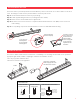
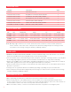
BRACKET SPACING Adjustable wall/ceiling brackets are furnished with all SL-Series Heaters. Brackets have positive stops at 30°and 45°. Brackets are positioned along the “T” slot on back of unit. You must maintain a minimum distance between the mounting brackets to ensure a stable installation. MODEL MINIMUM SPACING BETWEEN BRACKETS SL 16XX 12" (30.5cm) SL 24XX 20" (50.8cm) SL 30XX 30" (76.2cm) SL 40XX 30" (76.2cm) SL-Series Brackets are designed for two positive stop positions.
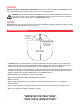
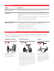
Heater must be installed with the quartz tube horizontally level. For maximum tube life, use a level to find the optimum position for the heater’s body. Always maintain the minimum clearances from the heater body to any combustible materials. LEVEL HERE 5-3/4" (14.6cm) MINIMUM 18" (45.7cm) FROM SIDE MINIMUM 18" (45.7cm) FROM SIDE 72" (1.8m) MINIMUM HEIGHT FROM FLOOR REPLACEMENT ELEMENT INSTALLATION (VISIT INFRATECH-USA.COM FOR VIDEO INSTRUCTIONS) Disconnect power at the breaker.
REPLACEMENT PARTS PART NUMBER PART DESCRIPTION QUANTITY 13-7008 End Reflector (Set of 2) 1 13-7004, 13-7002, 13-7000 Body Reflector - Fits (SL16), (SL24), (SL30/40) 1 13-7034, 13-7032, 13-7030 Lead Wire Set - Fits (SL16), (SL24), (SL30/40) 1 13-7020, 13-7022, 13-7023 Mounting Brackets (Set of 2) (Stainless Steel, Black) 1 13-7014, 13-7012, 13-7010 Grill Guard (SL16), (SL24), (SL30/40) 1 13-7028, 13-7026, 13-7024 Stainless Steel Trim (SL16), (SL24), (SL30/40) 1 13-7028BL, 13-7026BL, 13-7
TROUBLESHOOTING PROBLEM WHAT TO DO Heater does not glow • Check supply voltage to confirm it matches voltage of heating element. Low heat output • A 240V element connected to 110V or 208V will warm, but not glow orange, or generate sufficient heat for typical applications (matching your Voltage is extremely important). • If element is visibly orange, but there is insufficient heat, refer to the areas covered, with respect to conditions and mounting heights.
LIMITED PRODUCT WARRANTY Model #: Date of Purchase: Serial #: Purchased From: Thank you very much for purchasing a INFRATECH Quartz Tube Electric Heater. We have designed this heater to provide you and your family with many years of great outdoor experiences. Please fill in the Model and Serial number as well as date of purchase in the areas indicated above. Please save this information for future reference.