
IO 212-NG Installation Manual

2300 / IO 210 Manual
IM110107
RD: APR 2019
R.L. 20C
14
7. GAS SUPPLY PIPING
• All piping must be installed according to applicable local and national codes
• A listed flexible connector (field supplied) must be installed between the heater and gas
supply piping. For outdoor installation the connector must be in compliance with ANSI
Z21.75 / CSA 6.27. An optional 3/8” x 24” black finish flexible gas connector (part number
JL-0771-OD - approved Indoor/Outdoor) is available from Schwank / InfraSave.
• A drip-pocket must be provided in the gas piping at the inlet connection
• Provide a 1/8” NPT plugged tapping, accessible for test gage connection, immediately up-
stream of the gas supply connection to the heater.
• On propane-fired units, a main line filter is recommended (field supplied)
• Piping joint compounds must be resistant to the action of liquefied petroleum gases
• All piping joints must be tested for leaks with a soap and water solution.
CAUTION: DO NOT INSTALL ANY GAS PIPING IN HEAT ZONES
The maximum supply pressure must be limited to 14”w.c. (0.5 psi). If the line pressure is
above 14”w.c., then a separate pressure reducing regulator must be installed. The minimum
pressure at the inlet to the heater regulator must be equal to or greater than 6.0”w.c. for natu-
ral gas and 11.0”w.c. for propane gas.
Proper manifold pressure must be established during commissioning, and will be maintained
when the main burner is operating under the following supply pressure:
7.1 GAS PRESSURE
Natural Gas: Orifice sized for 1000 BTU/CU.FT.
Propane Gas: Orifice sized for 2500 BTU/CU.FT.
8. BASIC ELECTRICAL REQUIREMENTS - see also Section 16 page 25
All electrical installations must meet local codes and the latest edition ANSI/NFPA N0 70 in the
U.S.A. and Electrical Code PART 1 CSA C22.1 in Canada .
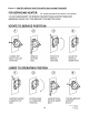
TRANSFORMER SPECIFICATIONS (field supplied)
Single heater requires 24 Volt, 60 Hz electrical transformer sized at 40 VA.
Multiple heaters in a zone are powered by a single transformer (field supplied). The proper
transformer is 24 Volt AC, 60 Hz, sized at 40VA for the first heater plus 20VA for each addition-
al heater in the zone - round up the calculated value to the next higher available sized trans-
former. For example, four heaters in a zone require a transformer of : 1 x 40VA + 3 x 20 VA =
100 VA . It is not recommended to install more than 12 heaters per zone.
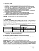
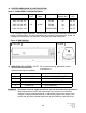
Table 5
LINE PRESSURE ”w.c. MANIFOLD PRESSURE ”w.c.
MODELS GAS TYPE MINIMUM MAXIMUM
AT GAS VALVE TEST PORT
NATURAL GAS
6.0 14.0 5.0
2312, 2313 / IO-212, IO-213
PROPANE GAS
11.0 14.0 10.0
2352 / IO-252 (2-Stage)
NATURAL GAS (ONLY)
6.0 14.0 5.0 High; 3.0 Low