
Installation Sheet


4
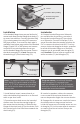
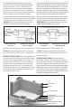
4. When mortar layer is dry, perform
necessary waterproofing (Liquid /Fabric
Waterproofing) as per local code. Ensure
waterproofing layer reaches the edge of
the hole in the drain body (C2).
4. Cuando el mortero este seco, realice
necesario impermeabilización (Liquida/
Tela impermeabilización) según las
normas locales. Asegure que la capa de
impermeabilización alcance el borde del
agujero en el cuerpo del desagüe (C2).
5. Set top threaded ring (C1) onto the bonded
ange drain body (C2) using thinset and
position to desired location within the drain
body (C2).
5. Fijar la parte superior roscada (C1) en el
bonded ange desagüe (C2) usando thinset y
posiciónelo a la ubicación deseada dentro del
desagüe (C2).
Note: When overall build up greater
than ¼” above waterproong is needed
(excluding nished oor material thickness)
use mortar to set top threaded ring (C1).
Tenga en cuenta: Cuando construya más que
¼” arriba impermeabilización es necesaria
(excluyendo material de piso terminado)
Utilice mortero para jar el anillo roscado.
6. Once the thinset/mortar is dry, thread
the throat (B) into top threaded ring (C1).
Adjust to the desired height. Turn clockwise
to lower, counter-clockwise to raise.
When determining desired height, include
thickness of thinset and nishing material.
6. Una vez el thinset/mortero este seco, rosca
el cuello (B) en la parte superior del anillo
roscado (C1). Ajustar a la altura deseada. Gire
hacia la derecha para bajar, hacia la izquierda
para subir. Cuando determine la altura, incluya
espesor del thinset y material terminado.
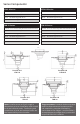
Liquid/Fabric
Waterproong
Suboor
Motar Bed
Backer Board
Waste Line Pipe
(C2) Bonded Flange
Drain Body
4
Liquid/Fabric
Waterproong
Motar Bed
Thinset/Motar
Waste Line Pipe
(C2) Bonded
Flange
Drain Body
(C1) Top Threaded
Ring
5
Bonded Flange
Drain Body
Waste Line Pipe
(B) Throat
(C2)
(C1)
6
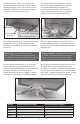
Model Overall Minimum Height Overall Maximum Height*
LTD 5 B 1” 2”
RTDB 15 ¹³⁄
¹⁶
” 1 ⁷⁄
¹⁶
”
TDB 15 1 ⁵⁄
¹⁶
” 1 ¹⁵⁄
¹⁶
”
TDB 20 1 ⁵⁄
¹⁶
” 2 ¹⁄
¹⁶
”