
Specification Sheet

S-TIF 6540 S-TIF 6548 S-TIF 6560
A
A
A
B
2
7
8
"
C
2"
3
4
"
6
1
2
"
2
1
2
"
2
3
8
"
1
11
16
"
Page 2 of 3REV. 08.01.15
Dimensions are subject to manufacturers tolerance and change without notice. We can assume no responsibility for use of superceded or void data.
Innity Drain
18 Secatoag Avenue
Port Washington, NY 11050
Phone: 516.767.6786
Fax: 516.740.3066
www.Innity Drain.com
NOTE: Installer must verify all rough-in
dimensions prior to installation and consult
local and national codes. Conformity and com-
pliance to local and national codes are the
responsibility of the installer.
Model
Number
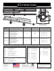
Complete Kit Contents
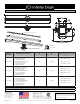
A
(Maximum Overall Length)
B
(Maximum Grate Length)
C
(Minimum Height Above Waterproong)
* All heights can be adjusted upwards an
additional 1-1/4”
S-TIF 6540
1 - TA 6540 Tile Insert Frame
1 - G 6540 PVC Channel
2 - E 65 PVC Stop End
1 - S 50 PVC Threaded Outlet
1 - HS 2 2” Hair Strainer
2 - CT 40 Channel Trim
1 - AKEY Lift Out Key
40” 39 7/8”
With CDI 22: 2-3/8”
With CDA 22: 1-7/8”
With CDP 22: 1-7/8”
S-TIF 6548
1 - TA 6548 Tile Insert Frame
1 - G 6548 PVC Channel
2 - E 65 PVC Stop End
1 - S 50 PVC Threaded Outlet
1 - HS 2 2” Hair Strainer
2 - CT 48 Channel Trim
1 - AKEY Lift Out Key
48” 47 7/8”
With CDI 22: 2-3/8”
With CDA 22: 1-7/8”
With CDP 22: 1-7/8”
S-TIF 6560
1 - TA 6560 Tile Insert Frame
1 - G 6560 PVC Channel
2 - E 65 PVC Stop End
1 - S 50 PVC Threaded Outlet
1 - HS 2 2” Hair Strainer
2 - CT 60 Channel Trim
1 - AKEY Lift Out Key
60” 59 7/8”
With CDI 22: 2-3/8”
W i t h C D A 2 2 : 1 - 7 / 8 ”
With CDP 22: 1-7/8”
Finishes
□ Satin Stainless □ Polished Stainless
□
□
□
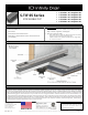
SECTION A-A
TIF-PL BOTTOM PLATE
TIF-PL TOP PLATE
#8 SCREWS
S 50 PVC THREADED OUTLET
E 65 PVC STOP END
2 INCH CLAMP DOWN DRAIN ASSEMBLY
(MATERIAL CAN BE CAST IRON, ABS OR PVC)
FINISHING MATERIAL (NOT INCLUDED)
TA 65 TILE INSERT FRAME
G 65 PVC CHANNEL
OPTIONAL PLATES FOR
LENGTH ADJUSTMENT