SCOM-100, User guide 2 SCOM-100 Alarming & remote control unit User guide Manual version: 1.04, 2/2007 Firmware version: 1.04 Disclaimer While every effort has been made to ensure that the information included in this guide is accurate and complete, no liability can be accepted for any errors or omissions. Infinite Ltd reserves the right to change the specifications of the hardware and software described in this guide at any time without prior notice.
SCOM-100, User guide 3 Contents 1. Device overview 1.1 Connections 1.2 LED indications 2. Wiring 2.1 Power supply 2.2 Digital inputs 2.3 Digital outputs 2.4 Analog inputs 2.4.1 Analog input 1 2.4.2 Analog input 2 2.5 I/O expansion power supply 2.6 GSM antenna 2.7 Microphone 3. Getting started 3.1 Preparing a SIM card 3.2 Installing the SIM card 3.3 First power up & factory settings 4. Device operation 4.1 SMS commands 4.2 Naming the unit 4.3 Configuring a digital input for alarming 4.3.
SCOM-100, User guide 4 4.4.5 Setting a digital output after a delay 4.4.6 Resetting a digital output after a delay 4.4.7 Digital output time based scheduling 4.4.8 Clearing the digital output configuration 4.5 Analog signal alarming 4.5.1 Analog input configuration 4.5.2 Setting alarm message’s texts for analog inputs 4.5.3 Clearing the analog input configuration 4.6 Special I/O Functions 4.6.1 ON/OFF and PID control 5. User administration 5.1 Create a new user 5.2 Change user configuration 5.
SCOM-100, User guide 5 6.5 Setting date & time 6.6 Setting a GSM PIN 7. Monitoring capabilities 7.1 Monitoring commands 7.2.1 Using the HyperTerminal for configuration 7.2.2 Using the SCOM-100 Configurator for configuration 8. Using the microphone input 9. Appendix 9.1 Command reference 9.1.1 General parameter settings 9.1.2 User configuration 9.1.3 Output control & configuration 9.1.4 Input configuration 9.1.5 I/O Functions 9.1.6 RTC & Time scheduling 9.1.7 Monitoring commands 9.2 Troubleshooting 9.
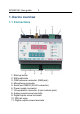
SCOM-100, User guide 6 1. Device overview 1.1 Connections 1: Start up button 2: SIM cardholder 3: GSM antenna connector (SMA jack) 4.
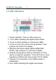
SCOM-100, User guide 7 1.2 LED indications 1: Power indicator: Turns on after power up. 2: Four LEDs indicating the digital output states. 3: Turns on while sending or receiving an SMS. 4: Turns on if an error occurs during operation. See sections 9.4 and 9.5 for details. 5: Monitors the device status (RUN/ MONITOR/ STOP). See sections 6.1 and 9.5 for details. 6. Flashes during device start up. Remains on if the device is ready for operation. Turns off if one or more operating conditions fail.
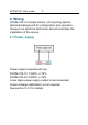
SCOM-100, User guide 8 2. Wiring SCOM-100 is a simple device, not requiring special technical background for configuration and operation. However an electrical technician should undertake the installation of the device. 2.1 Power supply Power supply requirements are: SCOM-100-12: 12VDC +/-15% SCOM-100-24: 24VDC +/-15% A low ripple power supply output is recommended. Output voltage stabilization is not required. See section 9.3.1 for details.
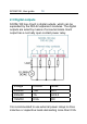
SCOM-100, User guide 9 2.2. Digital inputs SCOM-100 has 4 built in digital inputs, which can be expanded by the DIO-42 expansion modules. The digital inputs are wired by means of screw terminals. The digital inputs can be driven either by switches or transistors (open collector stages). Transducers with push-pull output are also applicable. Note: Output voltages higher than +5V or negative voltages (lower than GND) will be clamped from the comparator input protection zener.
SCOM-100, User guide 10 2.3 Digital outputs SCOM-100 has 4 built in digital outputs, which can be expanded by the DIO-42 expansion modules. The digital outputs are wired by means of screw terminals. Each output has a normally open contact power relay. Voltage Current Mode 250VAC 10A AC1 250VAC 1A AC2,3 150VDC 0.5A DC It is recommended to use external power relays to drive inductive or capacitive loads demanding more than 0.5A.
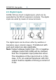
SCOM-100, User guide 11 2.4 Analog inputs SCOM-100 has 2 built in analog inputs (AI1, AI2). A1 is designed for voltage input and A2 for current input. 2.4.1 Analog input 1 Analog input 1 is a voltage input with two wiring options. Wiring option: A1A The input voltage range for this wiring option is 0-1VDC. The input resistance is 2K. The input voltage range is converted internally to a digital raw range of 0-4095.
SCOM-100, User guide 12 The circuit displayed on the center uses an external shunt resistor (~51.3 Ω) wired parallel to the input in order to measure current signals (e.g. 0-20/4-20mA). The circuit displayed on the right side of the page uses an external resistor (Rx) to measure DC voltage (Vx). Rx and Rin (2K) form a voltage divider. The following table illustrates the applicable resistor Rx values for different DC voltages: Vx 0..1V 0..5V 0..30V 0..60V 0..
SCOM-100, User guide 13 Wiring option: A1B Wiring option A1B is designed for 0..10VDC signal input through an internal 18K & 2K voltage divider. The input resistance is 20K.
SCOM-100, User guide 14 2.4.2 Analog input 2 Analog input 2 is designed as a current input. It can be used in conjunction with industry standard current loop transducers & sensors. Input impedance is 50Ω. The 0-20mA input is converted internally to a digital raw range of 0-4095. Note: Applying a voltage source to the current input AI2 may damage the internal 50Ω input resistor and respectively the entire input circuit.
SCOM-100, User guide 15 2.5 I/O expansion power supply SCOM-100 has two ways to provide power supply for the I/O expansion units. Bridge Vcc to Vex on the main SCOM-100 unit to power a limited number of I/O expansion units (up to 4), as shown below. (Power is then wired through the 6th pin on to the modular I/O expansion connector).
SCOM-100, User guide 16 Note: The Vex pin must not be connected when an external power source is connected on the expansion modules because the main SCO-100 unit will be damaged.
SCOM-100, User guide 17 2.6 GSM antenna An external GSM antenna should be used for locations with weak signal strength. SCOM-100 utilizes an SMA plug connector to connect a GSM antenna. The GSM antenna must be of appropriate frequency to cover the frequency band of your GSM provider’s network. 2.7 Microphone A two-pin connector is provided to connect an electret type microphone.
SCOM-100, User guide 18 3. Getting started 3.1 Preparing a SIM card Before installing the SIM card, use your phone to: 1. Clear the PIN code (no PIN needed). 2. Enter your name and phone number in the first place of the phonebook directory of the SIM card. Note: You can alternatively power up the unit without a SIM card and set the PIN number using a terminal program on a PC, or you can set a PIN in later configuration stages. 3.
SCOM-100, User guide 19 Insert the card into the tray and slide the tray with the card faced down into the cardholder. 3.3 First power up & factory settings Power up the unit and hold the startup button pressed until the ready LED starts blinking rapidly.
SCOM-100, User guide 20 4. Device operation 4.1 SMS commands The SCOM-100 unit accepts text SMS commands to configure operational parameters, control the unit’s operation modes, and control the unit’s outputs. Several commands can be packed in one SMS message. An SMS command has the following structure: XXXX,A..A,..,..,Z..Z XXXX: Command identification number 00009999 A..A, Z..Z: Command parameters The comma character (‘,’) is used as a separator in the command structure.
SCOM-100, User guide 21 spaces between except in text strings (eg. The name ‘My SCOM-100’ may contain spaces). Send the SMS to the SCOM-100 mobile phone number of the SIM. You will receive an SMS with the following response: COMMAND PROCESSED OK indicating that the device’s name is configured. 4.3 Configuring a digital input for alarming A digital input can be configured to initiate an alarm SMS transmission after a signal change. The following selections can be made: 1. Give a name to the digital input.
SCOM-100, User guide s: a: d: 22 Input signal name (Text: 0-15 characters, may include space characters) Transition selection (0: No alarm, 1: positive 2: negative 3: both transitions) Delay time in seconds (0-65535) The following example illustrates how to configure digital input 1 to initiate an alarm SMS after any signal transition, a delay time of 30 seconds and a signal name configured to “Door contact”.
SCOM-100, User guide 23 NEGATIVE ALARM If you close or open the contact without maintaining a delay time of 30 seconds, you won’t receive any alarm SMS message. 4.3.1 Setting alarm message’s texts You can set up to 128 custom text messages to be announced in an SMS alarm as a descriptive reason instead of the default causal text (e.g. POSITIVE ALARM).
SCOM-100, User guide 24 Let us specify alarm text messages for the previous example. The message for the positive (0 to 1) transition should be ‘Door is opened’. The respective message for the negative transition should be ‘Door is closed’. The commands to configure these text messages are: 0630,1,Door is opened; 0630,2,Door is closed Now we have to associate the text messages to the signal transitions of the example.
SCOM-100, User guide 25 Door contact Door is closed 4.3.
SCOM-100, User guide 26 4.4 Controlling the digital outputs 4.4.1 Setting a digital output SCOM-100 digital outputs are internal relay normally open contacts (see section 2.3). The command to set a digital output is: 1000,m,n 1000: Command ID m: Module number (0 for SCOM-100 main unit, 1-8 for DI-42 I/O expansion units) n: Output number (1-4 for SCOM-100 main unit, 1-2 for DI-42 I/O expansion units) Let us set output 2 of the main unit.
SCOM-100, User guide n: 27 Output number (1-4 for SCOM-100 main unit, 1-2 for DI-42 I/O expansion units) In our example the respective command to reset the output 2 of the main unit is: 1001,0,2 Send an SMS with the respective command to the device’s phone number. The output LED will switch off and you will hear the relay contact switch to the initial open state. You will then receive an “OK’ SMS message response. 4.4.
SCOM-100, User guide 28 The output LED 2 will switch on and you will hear the relay contact switch to a closed state. Now repeat the set/reset procedure of the last two examples. You will receive messages with a reverse behaviour of the output LED and relay contact. E.g. after a ‘SET’ command, the LED goes off and the relay contact switches to the open state and opposite. An output configured as a closed contact can be reconfigured to an open contact using the ‘Clear DO configuration’ command (see 4.4.
SCOM-100, User guide 29 This behavior is that of a monostable timer. The command to set an output with a pulse is: 1010,m,n,s 1010: Command ID m: Module number (0 for SCOM-100 main unit, 1-8 for DI-42 I/O expansion units) n: Output number (1-4 for SCOM-100 main unit, 1-2 for DI-42 I/O expansion units) s: Pulse duration in seconds (1-79200) Test the pulse command by sending an SMS: 1010,0,2,25 4.4.
SCOM-100, User guide 30 The command to set an output after an initial delay is: 1020,m,n,h,mn 1020: Command ID m: Module number (0 for SCOM-100 main unit, 1-8 for DI-42 I/O expansion units) n: Output number (1-4 for SCOM-100 main unit, 1-2 for DI-42 I/O expansion units) h: Delay on duration hours (0-21) mn: Delay on duration minutes (0-59) 4.4.6 Resetting a digital output after a delay A command is available to reset a digital output with an initial delay time.
SCOM-100, User guide 31 The command to reset an output after a delay is: 1021,m,n,h,mn 1021: Command ID m: Module number (0 for SCOM-100 main unit, 1-8 for DI-42 I/O expansion units) n: Output number (1-4 for SCOM-100 main unit, 1-2 for DI-42 I/O expansion units) h: Delay off duration hours (0-21) mn: Delay off duration minutes (0-59)
SCOM-100, User guide 32 4.4.7 Digital output time based scheduling Multivibrator A multivibrator is a continuous time based switching sequence as shown in the following diagram: Although the output’s switching is continuous, commands for temporary setting or resetting (1000, 1001) are also applicable and accepted by the device.
SCOM-100, User guide 33 Time schedule program Time schedule programs relate to absolute daytimes. Up to 80 time schedule programs can be stored in the SCOM-100 power fail safe memory, 10 programs for each day of a week (Sunday to Saturday), and 10 programs for an ‘everyday’ schedule. Every program permits up to 8 on switching sequences.
SCOM-100, User guide 34 1700,1,0,8:00-120,11:30-100;16:45-180 A schedule program can be attached the device’s outputs by using the following command: 1030,m,n,ID 1030: Command ID m: Module number (0 for SCOM-100 main unit, 1-8 for DI-42 I/O expansion units) n: Output number (1-4 for SCOM-100 main unit, 1-2 for DI-42 I/O expansion units) ID: Time schedule ID (1-10) A device output attached on a schedule ID will operate according to the following rules: 1.
SCOM-100, User guide 1701: P: 35 Command ID Factor in % (0-100%). The ON duration of each program sequence is calculated by multiplicating this factor with the initial sequence duration. Example: Reducing the total ON duration of program 3 to the half: 1701,3,50 4.4.
SCOM-100, User guide 36 4.5 Analog signal alarming 4.5.1 Analog input configuration The SCOM-100 analog inputs can be configured to initiate alarm SMS messages when preset alarm limit conditions (low & high alarm limits) are met. A user configurable scale can be defined to associate an analog input signal to physical units.
SCOM-100, User guide ALH: u: d: 37 Alarm high limit in physical units (number in the range of SCL to SCH with one optional decimal digit. Example: ALH = 121.5) Physical unit (0-15 characters) Delay time in seconds (0-65535) For example let us explain all the different parameter settings to use a 4-20mA, 0-10 bar pressure sensor wired on analog input 2 on the main unit (See section 2.4.2).
SCOM-100, User guide 38 The following diagram illustrates the conversion characteristic: The conversion values are given by the formula: Raw digital value:=4095 * Ix/20 Ix: Input current value (mA) According to the formula, a 4mA input is converted to: Raw digital value=4095*4/20 = 819 This is the value setting for SSL. A 20mA input is converted to a raw reading of 4095. This is the value setting for SSH. SCOM-100 physical scale values are limited to integer values between -100,000 and 100,000.
SCOM-100, User guide 39 1200,0,2,Pressure,819,4095,0,10000,2500, 8500,mBar,15 The low alarm limit is set to 2.5 Bar, the high alarm limit to 9.5 Bar. A 15 second delay is also set so that the input signal must persist in value and exceed alarm limits (low or high) for 15 seconds. If these clauses are met then an alarm SMS will be initiated. Note: Alarm annunciation is cancelled if the respective Scale (low or high) and limit alarm values (low or high) are equal. 4.5.
SCOM-100, User guide 40 4.5.3 Clearing the analog input configuration Any analog input configuration settings such as alarm, naming, messaging and scaling can be cleared using the command: 1210,m,n 1210: Command ID m: Module number (0 for SCOM-100 main unit, 1-4 for AI-4 expansion units) n: Input number (1-2 for SCOM-100 main unit, 1-4 for AI-4 expansion units) 4.5.4 Setting the analog inputs alarm deadband A special command is available to configure alarm deadband (hysteresis) for all analog inputs.
SCOM-100, User guide 41 4.6 Special I/O Functions 4.6.1 ON/OFF and PID control Up to four ON/OFF or PID control function blocks are available. Each block uses an analog input for measuring the process value and a digital output for control. Function block configuration 1250,id,m,n,m1,n1,sp,g,it,dt,ct,h 1250: Command ID. id: Function block ID (1-4). m: Module number (0 for SCOM-100 main unit, 1-4 for AI-4 expansion units). n: Input number (1-2 for SCOM-100 main unit, 1-4 for AI-4 expansion units).
SCOM-100, User guide dt: 42 ‘Derivative time’ (D) value between 1200 sec. A zero value disables the drivative part (not relevant for ON/OFF control).. ct: ‘Cycle time’ value between 1 and 15 minutes, representing the pulse width modulation period of the digital output (not relevant for ON/OFF control). h: ‘Hysteresis’ value in [%] of the analog input scale (0-20%) for ON/OFF control (not relevant for PID control). Changing the set point value 1255,id,sp 1255: Command ID. id: Function block ID (1-4).
SCOM-100, User guide 43 1252,id,m,n 1252: Command ID. id: Function block ID (1-4). m: Module number (0 for SCOM-100 main unit, 1-8 for DI-42 I/O expansion units) n: DI input number (1-4) The following command clears the digital input function. 1253,id 1253: Command ID. id: Function block ID (1-4). Clearing the Function block configuration The command erases the function block configuration and frees the function block instance and the respective I/O. 1260,id 1260: Command ID. id: Function block ID (1-4).
SCOM-100, User guide 44 5. User administration Up to 20 SMS users can be declared in a user list for an SCOM-100 unit. Only declared users can interact (send, receive SMS) with the unit. SCOM-100 features three user privileges reflecting different user rights. For each user the following privilege flag can be configured: 1. User administration. A user has the right for user administration (Create, Delete, Set privileges) or not. 2. Device configuration.
SCOM-100, User guide 45 5.2 Change user configuration A user with the user administration privilege can use this command to edit other user privileges. 0502,id,c1,c2,c3 0502: Command ID id: User ID (1-20) c1: User administration privilege (0 for ‘No’ 1 for ‘Yes’) c2: Device configuration privilege (0 for ‘No’ 1 for ‘Yes’) c3: Alarm SMS recipient (0 for ‘No’ 1 for ‘Yes’) 5.3 Delete a user A user with the user administration privilege can use this command to remove a user from the user list.
SCOM-100, User guide 46 n: DI input number (1-4) id: User ID (1-20) 5.4.2 Set an AI alarm recipient 1202,m,n,id 1202: Command ID m: Module number (0 for SCOM-100 main unit, 1-4 for AI-4 expansion units) n: AI input number (1-2 for SCOM-100 main unit, 1-4 for AI-4 expansion units) id: User ID (1-20) 5.4.3 Clear DI alarm recipients The command removes all recipients for a specific DI alarm.
SCOM-100, User guide 47 6. Device status & mode controls 6.1 Setting the device status A SCOM-100 unit has three operation states: 1. The RUN (Control) state: The unit sends alarm SMS and accepts output control commands. The Status LED is then on. 2. The MONITOR state: The unit sends alarm SMS. All outputs are reset to their initial state. Output control commands are executed by storing the output states internally. The actual output states are restored upon switching to the RUN state.
SCOM-100, User guide 48 The Status LED switches off and the unit enters the STOP state. 6.2 Controlling the device status A digital input can be used to switch between RUN and MONITOR mode for power saving purposes. 1105,m,n,v 1105: Command ID m: Module number (0 for SCOM-100 main unit, 1-8 for DI-42 I/O expansion units) n: DI input number (1-4) v: Input state for switching to MONITOR mode (0,1). The function can be deactivated with the ‘Clear DI configuration command (See 4.3.2). 6.
SCOM-100, User guide 49 0620 6.3.2 Response format The device acknowledgement SMS can be in verbose or brief format. The verbose format is informative text and is recommended for man to machine applications. Brief format is a briefly coded format for use in machine-tomachine applications. Verbose acknowledgement can be cancelled using the command: 0611 The verbose acknowledgement can be restored using the command: 0610 6.3.
SCOM-100, User guide 50 v: Remaining SMS number (04294967295) Remaining SMS messages limit reach will be acknowledged to users if a limit is set using command: 0600,l 0600: Command ID l: Remaining SMS alarm limit (04294967295) Remaining SMS alarm annunciation can be cancelled using the command: 0601 6.
SCOM-100, User guide 0783: p: 51 Command ID 4 number characters 7. Monitoring capabilities 7.1 Monitoring commands The following command invokes a response about device state and active I/O information: 5100 A typical response SMS is: UNIT:My SCOM-100 MODE:MONITOR Door contact (DI 0,1):OFF Several commands are available for monitoring the actual device configuration, I/O status and device status. See 9.1.6 command summary for more information on monitoring commands.
SCOM-100, User guide 52 7.2 Connecting a PC The SCOM-100 device can be connected to a PC via the device’s serial port and special serial cable. 7.2.1 Using the Hyperterminal for configuration Connect the SCOM-100 unit to a PC. Open the HyperTerminal and set up a new session. Press OK to create a new connection.
SCOM-100, User guide 53 Select a serial connection, choose the appropriate serial port and press ‘OK’.
SCOM-100, User guide 54 Open the ‘Properties’ menu and press the ‘ASCII Set up’ button. Check the option ‘Append line feeds to incoming line ends’ and press ‘OK’ to leave the Properties dialog. Type in: at and press .
SCOM-100, User guide 55 If a connection is established the answer is ‘OK’. If you don’t see your typed characters, give the following command to enable character echoing: Ate1 All configuration commands can be passed to the unit from the Windows HyperTerminal. The command structure is the same to that of the SMS commands, except the fact that they are embedded in an overall ‘atsms’ command.
SCOM-100, User guide 56 8. Using the microphone input A microphone input is provided for the temporary auditive room observation in a remote SCOM-100 site installation. An electret microphone must be connected to the respective input for using this option. SCOM-100 answers incoming voice calls from users with the administration priviledge. All remote control and alarming capabilities are temporary suspended during the auditive session. Any occuring alarms are transmitted after the session termination.
SCOM-100, User guide 57 9. Appendix 9.1 Command reference 9.1.
SCOM-100, User guide 58 Cmd Description Syntax 0611 Cancel Verbose Responses cmd 0620 Set acknowledgement SMS cmd 0621 Cancel acknowledgement SMS cmd 0630 Set Alarm Message Text cmd,id,s id:1-128, s:0-31 0650 Set Remaining SMS Counter cmd,v 0660 Merge Concurrent Alarms cmd 0661 Unmerge cmd Concurrent Alarms 0783 Set GSM PIN cmd,p Comments v:0-4294967295 p:4
SCOM-100, User guide 59 9.1.
SCOM-100, User guide 60 9.1.
SCOM-100, User guide 61 Cmd Description Syntax Comments 1070 Init DO as Open Contact cmd,m,n m:0-8, n:1-4 (base) or 1-2 (ext) 1071 Init DO as Closed Contact cmd,m,n m:0-8, n:1-4 (base) or 1-2 (ext) 1090 Clear DO cmd,m,n Configuration m:0-8, n:1-4 (base) or 1-2 (ext) 9.1.
SCOM-100, User guide Cmd Description 62 Syntax Comments 1201 Set AI Alarm Messages cmd,m,n,id1,id2 m:0-4, n:1-2 (base) or 1-4 (ext), id1/id2:0-128 1210 Clear AI Configuration cmd,m,n m:0-4, n:1-2 (base) or 1-4 (ext) 1800 Set analog IN deadband Cmd,d D:0-5% of the total scale with 0.1 steps 9.1.5 I/O Functions Cmd Description Syntax Comments 1250 Set ON/OFF cmd,id,m,n,m id:1-4, m,n:AI, - PID Control 1,n1,sp,g,it,dt, m1,n1:DO, Configuration ct,h sp:-100000-100000, g:0.0-100.
SCOM-100, User guide 63 Cmd Description Syntax Comments 1255 Set PID Control Set Point cmd,id,sp id:1-4, sp:-100000100000 1260 Clear PID cmd,id Control Configuration id:1-4 1105 Set DI for device Status control m:0-8, n:1-4, v:0-1 cmd,m,n,v 9.1.
SCOM-100, User guide 64 9.1.
SCOM-100, User guide Cmd 65 Description Syntax Comments 3050 Get DO settings cmd,m,n m:0-8, n:1-4 (base) or 1-2 (ext) 3100 Read DI cmd,m,n m:0-8, n:1-4 3110 Get DI Settings cmd,m,n m:0-8, n:1-4 3200 Read AI cmd,m,n m:0-4, n:1-2 (base) or 1-4 (ext) 3210 Get AI Settings cmd,m,n m:0-4, n:1-2 (base) or 1-4 (ext) 3250 Get ON/OFF - PID Settings cmd,id 3600 Get RTC Time cmd 3700 Get Time Schedule cmd,id 5000 Get HELLO cmd 5100 Get Current IO State (AI/DI/AO/DO) cmd id:1-4 id:1-10
SCOM-100, User guide 66 9.2 Troubleshooting The ready LED goes off after the start up sequence. Case 1: Error LED is off You started the unit for the first time and the SIM card does not contain a user name and phone number in the phone book directory. See chapter 3.1. Case 2: Error LED is on An error occurred during start up. See chapter 9.4 & 9.5. The unit does not respond to SMS at all. The unit does not register to the GSM provider network. Check if the ‘NETWORK’ LED is blinking.
SCOM-100, User guide 67 The unit does not send an alarm SMS after a digital input state changes. The device is in STOP mode. The respective input is not activated for alarming. Activate the input by sending the proper configuration command (See chapter 4.3). The analog value readings through the monitoring command seem not to be correct. Check sensor cabling for the corresponding channel (see chapter 2.4) Set the correct analog channel measurement parameters (see 4.5.1).
SCOM-100, User guide 68 9.3 Technical specifications 9.3.1 Main unit Protection IP20 Temperature range -10°C, +70°C, operating Dimensions 106 x 90 x 58 mm Weight 0.3 kg LED indications 4 digital input LED 4 digital output LED 6 control LED Mounting EN 60 715 TH35 DIN rails or direct wall mounting.
SCOM-100, User guide 69 Power supply & I/O: screw terminals GSM MODEM Quad Band (850/900/1800/1900MHz) SMS GSM Text Format 9.3.2 GE-DIO-42 Digital I/O Expansion module Protection IP20 Temperature range -10°C, +70°C, operating Dimensions 53 x 90 x 58 mm Mounting EN 60 715 TH35 DIN rails or direct wall mounting.
SCOM-100, User guide 9.
SCOM-100, User guide 71 9.5 Status LED indications 9.5.
SCOM-100, User guide 72 9.5.2 GE-DIO-42 Digital I/O expansion LED Indication POWER Presence of power supply voltage RST Digital output reset during STOP or MONITOR status 9.
SCOM-100, User guide 73 9.7 Setting an I/O expansion module address 9.7.1 GE-DIO-42 digital I/O expansion Module number 0 is reserved for the main unit. The module number (m, see sections 4.3 & 4.4) of an expansion module is determined by the DIP switch settings on the rear side of the module.
SCOM-100, User guide Dip switch settings 74 Module number (m) 1 2 3 4 5 6 7 8
SCOM-100, User guide 75 9.