
Datasheet

TLE7368
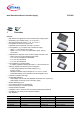
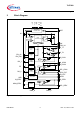
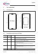
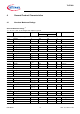
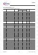
Pin Configuration
Data Sheet 7 Rev. 2.1, 2010-11-22
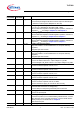
65IN_LDO2LDO2 input;
Connect this pin straight to the Buck converter output or add a dropper
in between to reduce power dissipation on the chip.
7 6 Q_LDO2 Voltage regulator 2 output;
3.3 V or 2.6 V, depending on the state of SEL_LDO2.
Block to GND with capacitor for stable regulator operation; selection of
capacitor
C
Q_LDO2
according to Chapter 4.4 and Chapter 6.
87Q_T1Tracking regulator 1 output;
Block to GND with capacitor for stable regulator operation; selection of
capacitor
C
Q_T1
according to Chapter 4.4 and Chapter 6.
98Q_T2Tracking regulator 2 output;
Block to GND with capacitor for stable regulator operation; selection of
capacitor
C
Q_T2
according to Chapter 4.4 and Chapter 6.
10 9 EN_uC Enable input microcontroller;
High level enables / low level disables the IC except the stand-by
regulators;
Integrated pull-down resistor
11 10 EN_IGN Enable input ignition line;
High level enables / low level disables the IC except the stand-by
regulators;
Integrated pull-down resistor
12 11 SEL_STBY Selection input for stand-by regulator;
Connect to GND to select 2.6 V output voltage for Q_STBY;
Connect straight to Q_STBY to select 1.0 V output voltage for Q_STBY
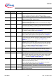
13 12 C1- Charge pump negative #1;
Connect a ceramic capacitor 100 nF, to C1+
14 13 C2- Charge pump negative #2;
Connect a ceramic capacitor 100 nF, toC2+
15 14 C1+ Charge pump positive #1;
Connect a ceramic capacitor 100 nF, to C1-
16 15 C2+ Charge pump positive #2;
Connect a ceramic capacitor 100 nF, to C2-
17 16 CCP Charge pump output;
Connect a ceramic capacitor, 220 nF, to GND;
Used for internal IC supply, do not use for other circuitry.
18 17 GND_P Power ground;
Exclusive GND connection of charge pump;
Connect this pin to the power ground star point on the PCB.
– 18, 19 GND_A Analog ground connection;
Connect to exposed pad.
19, 20 20, 21, 22 IN Buck regulator input;
Connect to a pi-filter (or if not used to battery) with short lines; connect
filter capacitors in any case with short lines; connect a small ceramic
directly at the pin; For details refer to Chapter 6.
Interconnect the pins.
21 – N.C. Internally not connected; Connect to GND_A.
Pin
(TLE7368G)
Pin
(TLE7368E)
Symbol Function