
Datasheet

TLE7368
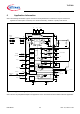
Detailed Internal Circuits Description
Data Sheet 31 Rev. 2.1, 2010-11-22
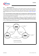
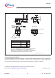
5.9 Monitoring Circuit
The monitoring block within the TLE7368 detects an undervoltage at the stand-by regulator output and is able to
distinguish between two different undervoltage situations. When the stand-by output gets back into regulation after
an undervoltage event, the timing on the MON_STBY output signal indicates the kind of undervoltage scenario
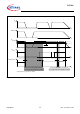
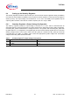
which has happened before. The behavior of the monitoring block is also described in Figure 6 and Figure 7
below.
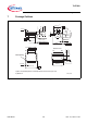
In case of an undervoltage at the stand-by regulator with the 5 V regulator LDO1 in regulation (which means that
RO_1 = HIGH) the monitoring circuit has basically a power fail functionality which means that the MON_STBY
output will be LOW just as long as the undervoltage at the stand-by output occurs. As soon as Q_STBY is coming
back into regulation MON_STBY turns high again.
When the 5 V regulator is out of regulation (RO_1 = LOW), e.g. in case of EN_uC = EN_IGN = LOW, the
MON_STBY will turn LOW again if an undervoltage event happens at Q_STBY. The difference to the scenario
described above is now that when Q_STBY gets back into regulation the toggling of the MON_STBY output to
HIGH is coupled with the 5 V Reset line, RO_1, turning HIGH. In detail, the MON_STBY line turns high delayed
by
t
MON_STBY
after the Reset line RO_1 had gone high.
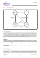
Figure 6 Stand by Monitor State Diagram
MON = High
V
Q_STBY
< V
MON, Q_STBY, de
and
RO_1 = High
Monitor timing
= don’t care
MON = Low
Monitor timing
= no delay
*)
MON = Low
Monitor timing
= delay
**)
*)
power fail functionionality
**)
power on reset functionality
V
Q_STBY
> V
MON, Q_STBY, in
and
RO_1 = High
V
Q_STBY
< V
MON, Q_STBY, de
and
RO_1 = Low
V
Q_STBY
> V
MON, Q_STBY, in
and
RO_1 = High
V
Q_STBY
< V
MON, Q_STBY, de
and
RO_1 = Low
V
Q_STBY
> V
MON, Q_STBY, in
and
RO_1 = Low