
Datasheet

Data Sheet 32 Rev. 2.1, 2010-11-22
TLE7368
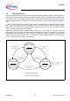
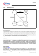
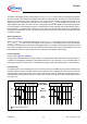
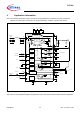
Detailed Internal Circuits Description
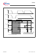
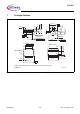
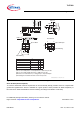
Figure 7 Stand by Monitor Timing Diagram
Power on reset functionality, with RO_1
low during under voltage at Q_STBY
V
IN_STBY
t
*)
output pulled to e.g. Q_LDO1 by 10kOhm
V
RO_1
*)
t
V
MON_STBY
*)
t
V
Q_STBY
t
t
MON_STBY
< t
RR, MON_STBY1
V
MON, Q_STBY, in
V
MON, Q_STBY, de
t
RR, MON_STBY
t
RR, MON_STBY
t
RR, MON_STBY
Power fail functionality, w/o delay, with
RO_1 high during under voltage at Q_STBY
V
IN
t