
Datasheet

Data Sheet 5 Rev. 1.0, 2009-06-01
TLE7276-2
Pin Configuration
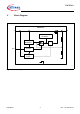
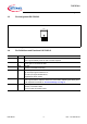
3.3 Pin Assignment PG-TO252-5
Figure 3 Pin Configuration (top view)
3.4 Pin Definitions and Functions PG-TO252-5
Pin No. Symbol Function
1IInput
block to ground directly at the IC with a ceramic capacitor
2n.c.non connected
can be open or connected to GND
3GNDGround
internally connected to heat slug
4ENEnable Input
high level input signal enables the IC;
low level input signal disables the IC;
integrated pull-down resistor
5QOutput
block to ground with a capacitor close to the IC terminals, respecting the values given
for its capacitance and ESR in “Functional Range” on Page 6
Heat Slug – Heat Slug
internally connected to GND;
connect to GND and heatsink area
n.c.
EN
Q
GND
I