
Datasheet

TLE 7241E
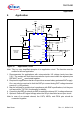
Application
Data Sheet 67 Rev. 1.1, 2009-01-19
6.1 Layout Notes
• The POS pin should be connected directly to the external sense resistor with a
dedicated trace.
• The NEG pin should be connected directly to the external sense resistor with a
dedicated trace.
• The POS pin trace should be routed near the NEG pin trace and both traces should
not be routed near noise inducing signal lines and/or components (SPI clock signals,
switching power supply inductors, etc.).
• For best accuracy, the external sense resistor should be placed near the IC.
• A capacitor should be connected between the V
DD
pin and ground near the IC.
• A capacitor should be connected between the V
SO
pin and ground near the IC.
• A capacitor should be connected between the BAT pin and ground near the IC.
• A capacitor should be connected between the REF pin and ground near the IC.
• The exposed lead frame should be connected to a large area ground plane and to
the pins PGND1, PGND2.
• The GND pin should be connected directly to the ground plane.