
Datasheet
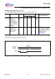
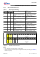
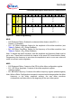


B15 B14 B13 B12 B11 B10 B9 B8 B7 B6 B5 B4 B3 B2 B1 B0
Channel
Enhanced Dither
MOSI CH 0 1 ED DA4 DA3 DA2 DA1 DA0 DF6 DF5 DF4 DF3 DF2 DF1 DF0
MISO CH 0 1 ED DA4 DA3 DA2 DA1 DA0 DF6 DF5 DF4 DF3 DF2 DF1 DF0
Channel
Enhanced
Dither
Dither
Configuration
Dither
Configuration
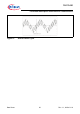
Dither FrequencyDither Frequency
Dither AmplitudeDither Amplitude
TLE 7241E
Functional Description and Electrical Characteristics
Data Sheet 55 Rev. 1.1, 2009-01-19
Figure 26 Dither Programming
MOSI
• B12 Enhanced Dither: Enables the enhanced dither feature when ED = 1,
Default = 0 (disabled)
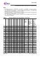
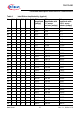
• B11 - B7 Dither Amplitude: Setting for the amplitude of the dither waveform (see
Table 3), Default = 00
H
(Dither Disabled)
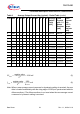
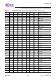
• B6 - B0 Dither Frequency: Setting for the frequency of the dither waveform (see
Table 4), Default = 00
H
(Dither Disabled)
Note: To disable the dither waveform, both the amplitude and frequency fields must be
set to zero. These fields must both be cleared in the same SPI communication frame.
Programming the frequency to zero when the amplitude is set to a non-zero value will
result in incorrect current regulation.
MISO
• B12 Enhanced Dither: Contents of the ED bit of the dither configuration register
• B11 - B7 Dither Amplitude: Contents of the dither amplitude register
(shadow register)
• B6 - B0 Dither Frequency: Contents of the dither frequency register (shadow register)
Note: When a Dither Configuration command is received which changes either the dither
frequency or the dither amplitude settings, the new dither waveform
characteristics will take effect at the beginning of the next dither period.