
Datasheet


Data Sheet 52 Rev. 1.1, 2009-01-19
TLE 7241E
Functional Description and Electrical Characteristics
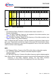
5.6.2 SPI Command Structure
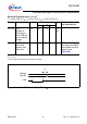
Table 1 SPI Command Summary
Channel Instruction ID Command Type MISO Response - Next
CSB Assertion
B15 B14 B13
0 0 0 Average Current Set Point -
CH#1
Average Current Verification
and Status - CH#1
0 0 1 Dither Configuration - CH#1 Dither Config Verification
CH#1
0 1 0 General Configuration -
CH#1
General Config Verification
CH#1
0 1 1 Read Register - CH#1 Register Contents - CH#1
1 0 0 Average Current Set Point -
CH#2
Average Current Verification
and Status - CH#2
1 0 1 Dither Configuration - CH#2 Dither Config Verification
CH#2
1 1 0 General Configuration -
CH#2
General Config Verification
CH#2
1 1 1 Read Register - CH#2 Register Contents - CH#2
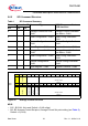
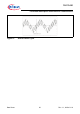
B15 B14 B13 B12 B11 B10 B9 B8 B7 B6 B5 B4 B3 B2 B1 B0
Channel
MOSI CH 0 0 X X X D9 D8 D7 D6 D5 D4 D3 D2 D1 D0
MISO CH 0 0EDGCORDCLPD9D8D7D6D5D4D3D2D1D0
Channel
Diagnostic Error
Command out
of Range
Dither clipping
I average
Average Current
Setpoint
I average
Average Current
Setpoint
Figure 25 Average Current Set Point
MOSI
• B12 - B10 NU: Not used, Default = 0 (40 mVpp)
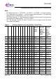
• B9 - B0: Average Current Set point, Average Current Set point setting (see Table 2),
Default = 0 (0 mA)