
Datasheet

Data Sheet 24 Rev. 1.1, 2009-01-19
TLE 7241E
Functional Description and Electrical Characteristics
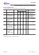
Diagnostics Timing Diagrams
V
POS -
V
NEG
Output transistor
state
off
on
Load State
ok
open
OL/SGx latched
fault state
tos(on)
CSB
MOSI
OPEN CIRCUIT / SHORT TO GROUND FAULT - OCCURS & CLEARS WHILE ON
MISO
t < tos(on)
OL/SGx
fault state
G.C.
cmd
G.C.
response
OLSG=0
G.C.
cmd
G.C.
respons e
OLSG=0
G.C.
cmd
G.C.
respons e
OLSG=1
G.C.
cmd
G.C.
respons e
OLSG=1
G.C.
cmd
G.C.
response
OLSG=0
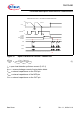
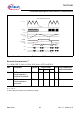
The Latched Fault State is sampled and stored in the SPI transmit register at the points marked with “ “ .
Figure 8 Open Load / Short to Ground Fault - Channel On
CSB
OPEN LOAD / LOAD SHORTED TO GROUND FAULT - OCCURS WHILE ON THE
N
CHANNEL IS TURNED OFF
MOSI
MISO
t os(off )=60µs
tos(on) = 12ms
V
POSx -
V
NEGx
LS-Switch
x
state
off
on
Load State
ok
open
OL/SGx
fault state
OL/SGx la tche d
fault state
G.C.
cmd
G.C.
respons e
OLSG=0
G.C.
cmd
G.C.
response
OLSG=1
A.C. cmd
Ia v= 0 ma
A.C.
response
ED G=1
G.C.
cmd
G.C.
response
OLSG=1
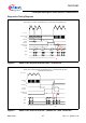
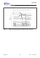
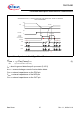
The Latched Fault State is sampled and stored in the SPI transmit register at the points marked with “ “ .
Figure 9 Open Load / Short to Ground - Channel On Then Turned Off