
Datasheet

V
POSx -
V
NEG x
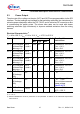
LS-Switch
state
off
on
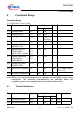
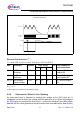
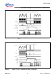
Vpwr
14 V
Vov
OVER-VOLTAGE FAULT
t < tov
Vov-ovhyst
TLE 7241E
Functional Description and Electrical Characteristics
Data Sheet 17 Rev. 1.1, 2009-01-19
Figure 4 Overvoltage Shutdown
T
j
= -40 to 150 °C; V
BAT
= 9 V to 18 V; V
DD
= 4.75 V to 5.25 V
Pos. Parameter Symbol Limit Values Unit Test Conditions
and Instructions
Min.
2) T
J
= 25 °C
Typ.
2)
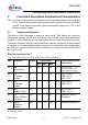
BAT Overvoltage
Shutdown
OV 30 35 40 Vdc Ramp up BAT until
outputs Off
BAT Overvoltage
hysteresis
OV
HYST
– 1.0 – Vdc Ramp BAT down
until outputs On
3) Not subject to production test, specified by design.
OUTx Active
Clamp Voltage
V
clamp
50 53 60 V I
d
= 20 mA, output
off
3)
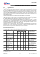
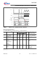
5.4.2 Overcurrent / Short to V
BAT
Sensing
An overcurrent fault is detected by sensing the voltage at the POS input pin. A
comparator is used to detect the voltage while the gate drive is on. When the voltage at
the POS input pin exceeds the short circuit / overcurrent threshold (see table below,
Item 5.4.2.3) for a time greater than the short sense time (see table below, Item 5.4.2.1)
Electrical Characteristics
1)
1) Positive current flow is into the device.
Max.
5.4.1.1
5.4.1.2
5.4.1.3