
Datasheet

Data Sheet 16 Rev. 1.1, 2009-01-19
TLE 7241E
Functional Description and Electrical Characteristics
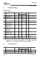
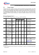
5.4 Protection and Control
T
j
= -40 to 150 °C; V
BAT
= 9 V to 18 V; V
DD
= 4.75 V to 5.25 V
Pos. Parameter Symbol Limit Values Unit Test Conditions and
Instructions
Min.
2) T
J
= 25 °C
Typ.
2)
POS/NEG
IBIAS
POS/NEG
IBIAS
-500 – 500 μA DAC command =3FF
POS=NEG=0V &
POS=NEG=17V
POS/NEG
LEAKAGE
POS/NEG
LEAKAGE
20
-20
40
0
60
20
μA
μA
Fault typing bit = 0, Zero
Current,
POS = NEG = 14 V
Fault typing bit = 1, Zero
Current,
POS = NEG = 14 V
Note: Integrated protection functions are designed to prevent IC destruction under fault
conditions described in the data sheet. Fault conditions are considered as outside
normal operating range. Protections functions are not designed for continuous
repetitive operation.
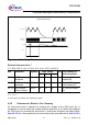
5.4.1 Overvoltage Sensing and Protection
When the voltage on the BAT pin exceeds the Overvoltage Shutdown Threshold (see
table below, Item 5.4.1.1), the output channel will shut off to protect the IC from
excessive power dissipation. A short filter with a typical value of 6.5 μs is included to
prevent undesired shutdown due to short transient voltage spikes. Although SPI
communication will remain functional, the output will remain off. The device will resume
normal operation when the BAT voltage has dropped below the overvoltage hysteresis
level. Note that the programmable registers are not reset, and the dither counter
continues to operate during an overvoltage event.
Both channels are disabled when an overvoltage condition is detected.
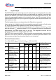
Electrical Characteristics
1)
1) Positive current flow is into the device.
Max.
5.4.1
5.4.2