
Datasheet

TLE 7241E
Functional Description and Electrical Characteristics
Data Sheet 15 Rev. 1.1, 2009-01-19
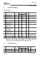
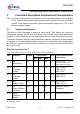
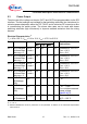
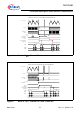
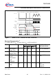
5.3 Power Output
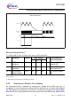
The slew rate of the voltage on the pins OUT1 and OUT2 are programmable via the SPI
interface. The fast settings are intended for fast switching solenoids (low inductance) to
minimize power dissipation within the TLE
7241E, and to minimize DC current error due
to overshooting the switch points. The slower slew rates can be used with slower
switching solenoids (high inductance) to improve radiated emissions from the wiring
harness.
T
j
= -40 to 150 °C; V
BAT
= 9 V to 18 V; V
DD
= 4.75 V to 5.25 V
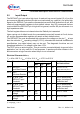
Pos. Parameter Symbol Limit Values Unit Test Conditions and
Instructions
Min.
2) T
J
= 25 °C
Typ.
2)
OUTx rise and
fall times Slew
Rate reg = 0
OUTx
t
R
and t
F
0.25 0.5 1 μs Threshold: 4 V to 10 V
V
BAT
= 14 V;
R
load
= 5 Ω
OUTx rise and
fall times Slew
Rate reg = 1
OUTx
t
R
and t
F
0.5 1 2 μs Threshold: 4 V to 10 V
V
BAT
= 14 V;
R
load
= 5 Ω
OUTx rise and
fall times Slew
Rate reg = 2
OUTx
t
R
and t
F
1 2 4 μs Threshold: 4 V to 10 V
V
BAT
= 14 V;
R
load
= 5 Ω
OUTx rise and
fall times Slew
Rate reg = 3
OUTx
t
R
and t
F
2.5 5 10 μs Threshold: 4 V to 10 V
V
BAT
= 14 V;
R
load
= 5 Ω
OUTx Output
Off Leakage
(00
H
)
I
DSS
– – 10 μA V
DS
= 24 V
OUTx Output
Off Leakage
(00
H
)
I
DSS
– – 3 mA V
DS
= V
CLAMP
- 1V
V
CLAMP
is the measured
clamp voltage
(
Item 5.4.1.3)
3) Electrical Distributions must be performed on this parameter as defined in the AEC-Q100 Specification
Table
2 test 27.
OUTx
3)
Driver
on Resistance
R
DS(ON)
– 240 450 mΩ Driver on Resistance
@
T
J
= 150 °C
Electrical Characteristics
1)
1) Positive current flow is into the device.
Max.
5.3.1
5.3.2
5.3.3
5.3.4
5.3.5
5.3.6
5.3.7