
Datasheet

TLE 7241E
Functional Description and Electrical Characteristics
Data Sheet 13 Rev. 1.1, 2009-01-19
5 Functional Description and Electrical Characteristics
Note: The listed characteristics are ensured over the operating range of the integrated
circuit. Typical characteristics specify mean values expected over the production
spread. If not otherwise specified, typical characteristics apply at
T
A
= 25 °C and
the given supply voltage.
5.1 Supply and Reference
The device has incorporated a power-on reset circuit. This feature will reset the
commanded average current to 0 mA (device off), and will reset the programmable
registers to their default values. The fault register bits are reset during power on reset.
The device will remain off until a valid command is received. The device will also be reset
in the case of an undervoltage condition on the pin
V
DD
. Note that if the voltage on the
pin REF pin is greater than the voltage on the pin
V
DD,
a current will flow from the REF
pin to the
V
DD
pin.
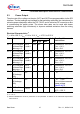
T
j
= -40 to 150 °C; V
BAT
= 9 V to 18 V; V
DD
= 4.75 V to 5.25 V
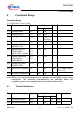
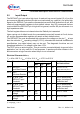
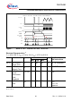
Pos. Parameter Symbol Limit Values Unit Test Conditions and
Instructions
Min.
2) Target @T
J
= 25 °C
Typ.
2)
REF
Bias Current
I
REF
-20 – 20 μA V
REF
= 2.5 V
(includes leakage current
and a small current sink)
V
DD
5 V Supply
Current
I
DD
– – 15 mA V
DD
= 5.25 V;
CSB = 5.0 V;
DAC = 3FF
V
SO
I/O Supply
Current
I
SO
– – 1 mA V
SO
= 5.25 V;
CSB = 5.0 V
BAT
Supply Current
I
BAT
– – 1 mA V
DD
= 5.25 V;
CSB = 5.0 V
V
DD
Power-On Reset
Threshold
V
POR
2.5 – 3.5 V Power-On Reset
Threshold
Internal
Reference
Voltage
V
IREF
2.45 2.5 2.55 V Tested at wafer test.
Electrical Characteristics
1)
1) Positive current flow is into the device.
Max.
5.1.1
5.1.2
5.1.3
5.1.4
5.1.5
5.1.6