
Datasheet

SPI Driver for Enhanced Relay Control
SPIDER - TLE7231G
Serial Peripheral Interface (SPI)
Datasheet 24 Rev. 1.1, 2011-04-12
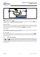
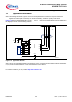
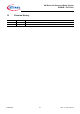
Figure 12 Daisy Chain Configuration
In the SPI block of each device, there is one shift register where one bit from SI line is shifted in each SCLK. The
bit shifted out can be seen at SO. After 8 SCLK cycles, the data transfer for one device has been finished. In single
chip configuration, the CS
line must transit from low to high to make the device accept the transferred data. In
daisy chain configuration the data shifted out at device #1 has been shifted in to device #2. When using three
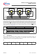
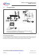
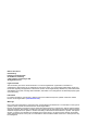
devices in daisy chain, three times 8 bits have to be shifted through the devices. After that, the MCS
line must
transit from low to high (see Figure 13).
Figure 13 Data Transfer in Daisy Chain Configuration
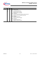
9.3 SPI Protocol
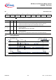
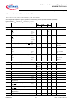
The SPI protocol of the TLE7231G provides two registers. The input register and the diagnosis register. The
diagnosis register contains four pairs of diagnosis flags, the input register contains the input multiplexer
configuration. After power-on reset, all register bits are cleared to 0.
SI
76543210
IN3 IN2 IN1 IN0
SI
device 1
SPI
SCLK
SO
CS
SI
device 2
SPI
SCLK
SO
CS
SI
device 3
SPI
SCLK
SO
CS
MO
MI
MCS
MCLK
SPI _DasyChain.emf
MI
MO
MCS
MCLK
SI device 3 S I devi ce 2 SI device 1
SO device 3 SO device 2 S O device 1
time
SPI _DasyChain2. emf