
Datasheet

SPI Driver for Enhanced Relay Control
SPIDER - TLE7231G
Power Stages
Datasheet 14 Rev. 1.1, 2011-04-12
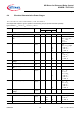
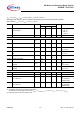
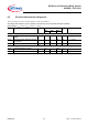
6.4 Electrical Characteristics Power Stages
V
DD
= 3.0 V to V
DDA
, V
DDA
= 4.5V to 5.5V, T
j
= -40 °C to +150 °C
All voltages with respect to ground, positive current flowing into pin (unless otherwise specified)
typical values:
V
DD
= 5.0 V, V
DDA
= 5.0 V, T
j
= 25 °C
Pos. Parameter Symbol Limit Values Unit Conditions
Min. Typ. Max.
Power Supply
6.4.1 Digital supply voltage
V
DD
3. 0 – 5.5 V –
6.4.2 Digital supply current all channels
ON
I
DD(ON)
––0.5mAV
DD
= V
DDA
= 5 V
V
RST
= V
CS
= V
DD
V
SCLK
= 0 V
V
IN
= 0 V
6.4.3 Digital supply idle current
I
DD(idle)
––
20
20
40
µA f
SCLK
= 0 Hz
V
RST
= V
CS
= high
T
j
= 25 °C
1)
T
j
= 85 °C
1)
T
j
= 150 °C
6.4.4 Digital supply sleep current
I
DD(sleep)
––
5
5
20
µA
V
RST
= 0 V
T
j
= 25 °C
1)
T
j
= 85 °C
1)
T
j
= 150 °C
6.4.5 Digital power-on reset threshold
voltage
V
DD(PO)
––3.0V–
6.4.6 Analog supply voltage
V
DDA
4.5 – 5.5 V –
6.4.7 Analog supply current all channels
ON
I
DDA(ON)
––5mA–
6.4.8 Analog supply idle current
I
DDA(idle)
––
25
µA V
CS
= V
DD
V
SI
= 0 V
V
SCLK
= 0 V
T
j
= 25 °C
1)
T
j
= 85 °C
1)
T
j
= 150 °C
6.4.9 Analog supply sleep current
I
dd(sleep)
––
5
5
20
µA
V
CS
= V
DD
V
RST
= 0 V
T
j
= 25 °C
1)
T
j
= 85 °C
1)
T
j
= 150 °C
6.4.10 Analog power-on reset threshold
voltage
V
DDA(PO)
––4.5V–
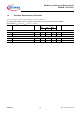
Output Characteristics
6.4.11 On-State resistance per channel
R
DS(ON)
–
1.0
2.0 2.2
Ω
I
L
= 250 mA
T
j
= 25 °C
1)
T
j
= 150 °C
6.4.12 Nominal load current
I
D(nom)
320 340 – mA
2)