
Datasheet

Datasheet 11 Rev. 1.1, 2011-04-12
SPI Driver for Enhanced Relay Control
SPIDER - TLE7231G
Power Supply
5 Power Supply
The TLE7231G is supplied by two power supply lines V
DD
and V
DDA
. The digital power supply line V
DD
is designed
to be functional at a very wide voltage range. The analog power supply
V
DDA
supports 5 V supply.
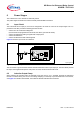
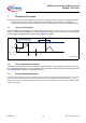
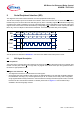
Power-on reset functions have been implemented for both supply lines. After start-up of the power supply, all SPI
registers are reset to their default values and the device remains in idle mode. Capacitors at pins
V
DD
- GND and
V
DDA
- GND are recommended.
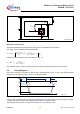
A reset pin is available. At low logic level at this pin, all registers are set to their default values and the quiescent
supply currents are minimized.
The
V
DD
supply line is used for the I/O buffer circuits of the SPI pins, therefore the voltage on the SO pin is always
related to this supply voltage. A capacitor between pins
V
DD
and GND is recommended (especially in case of EMI).
To enable the Daisy chain functionality it is necessary to have
V
DD
and V
DDA
in the specified functional range.
The device provides a sleep mode to minimize current consumption, which also resets the register banks. It is
controlled by a low active reset pin (RST) which disables the device and minimize the current consumption. The
table below gives an overview of the different power modes.
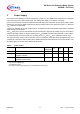
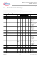
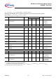
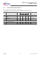
Table 2 Power modes
1)
1) low: pin input is digital low,
high: pin input is digital high,
X: pin state don’t care,
ON: voltage on this analog supply pin is in the specified functional range
Power mode State Description RESET
(low active)
V
DD
V
DDA
SCLK
SLEEP Device at minimum current consumption low X X 0 Hz
IDLE Device operational, all channels OFF no
diagnosis activated
high ON ON 0 Hz
ON Device operational with enabled channels and
diagnostic currents active
high ON ON 5 MHz
(max)