
Datasheet

Data Sheet 23 V2.1, 2008-04-30
TLE183F
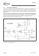
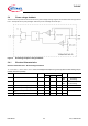
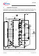
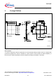
5.4 Phase voltage feedback
The TLE7183F incorporates an fast conversion of the phase voltages into logic signals. The threshold values are proportional
to V
DH
. The outputs are 5V push pull stages. When they are not used they can be left open.
Figure 5 Block diagram phase voltage feedback
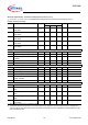
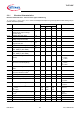
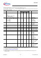
5.4.1 Electrical Characteristics
Electrical Characteristics - Phase Voltage Feedback
V
S
= 5.5 to 20V, T
j
= -40 to +150°C, F
PWM
< 25kHz, all voltages with respect to ground, positive current flowing into pin
(unless otherwise specified)
Pos. Parameter Symbol Limit Values Unit Conditions
Min. Typ. Max.
5.4.1
Low level threshold V
ILfb
35 40 45 % of
VDH
VDH>5.5V
V
SHX
decreasing
5.4.2 High level threshold
V
IHfb
55 60 65 % of
VDH
VDH>5.5V
V
SHX
decreasing
5.4.3 High level output voltage of x_fb
V
OHfb
4.0 5.2 V I= -0.5mA
5.4.4 Low level output voltage of x_f V
OLfb
-0.1 0.2 V I= 0.5mA
5.4.5 Propagation delay time incl. rise or fall
time
t
PDfb
110 ns C
LOAD
<100pF
5.4.6 Matching of propagation delay time t
dPDfb
30 ns