
Datasheet

Data Sheet 15 V2.1, 2008-04-30
TLE7183F
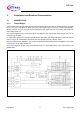
Description and Electrical Characteristics
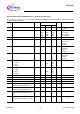
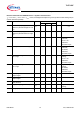
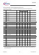
5.1.34 Absolute input propagation time
difference (all channel high off - low
on)
t
P(ahfln)
– – 150 ns C=22nF; R
Load
=1Ω
5.1.35 Absolute input propagation time
difference (all channel low off - high
on)
t
P(alfhn)
– – 150 ns C=22nF; R
Load
=1Ω
5.1.36 Wake up time; INH low to high
t
INH_Pen
– – 20 ms Driver fully
functional;
Vs=6.5...8V;
ENAx=low;
CPx=CBx=4.7µF
5.1.37 Wake up time; INH low to high
t
INH_Pen
– – 10 ms Driver fully
functional;
VS=8..20V;
ENAx=low;
CPx=CBx=4.7µF;
5.1.38 Wake up time logic functions; INH
low to high
t
INH_log
– – 10 ms diagnostic, OpAmp
working;
Vs=6.5...8V;
ENAx=low;
CPx=CBx=4.7µF
5.1.39 Wake up time logic functions; INH
low to high
t
INH_log
––5msdiagnostic, OpAmp
working;
VS=8..20V;
ENAx=low;
CPx=CBx=4.7µF
5.1.40 INH propagation time to disable the
output stages
t
INH_P(O)
– – 10 µs Vs=5.5..8V
5.1.41 INH propagation time to disable the
output stages
t
INH_P(O)
––8µsVs=8..20V
5.1.42 INH propagation time to disable the
entire driver IC
t
INH_P(IC)
––300µs–
5.1.43 Supply voltage V
s
for Wake up V
VsWU
6.5 – – V diagnostic, OpAmp
working;
5.1.44 Charge pump frequency
f
CP
38 55 72 kHz –
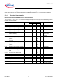
Electrical Characteristics MOSFET drivers - Dynamic Characteristics
V
S
= 5.5 to 20V, T
j
= -40 to +150°C, F
PWM
< 25kHz, all voltages with respect to ground, positive current flowing into pin
(unless otherwise specified)
Pos. Parameter Symbol Limit Values Unit Conditions
Min. Typ. Max.