
Datasheet


TLE6368-G2
Data Sheet 15 Rev. 2.32, 2010-10-19
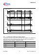
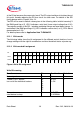
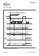
Figure 6 Window watchdog timing definition
Figure 6 shows some guidelines for designing the watchdog trigger timing taking the
oscillator deviation of different devices into account. Of importance (w.c.) is the
maximum of the closed window and the minimum of the open window in which the trigger
has to occur.
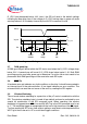
The length of the OW and CW can be modified by SPI command. If a change of the
window length is desired during the Watchdog function is operating please send the SPI
command with the new timing with a “Watchdog trigger Bit” D15=1. In this case the next
CW will directly start with the new length.
A minimum time gap of > 1/48 of the actual OW/CW time between a “Watchdog disable”
and ’Watchdog enable’ SPI-command should be maintained. This allows the internal
Watchdog counters to be resetted. Thus after the enable command the Watchdog will
start properly with a full CW of the adjusted length.
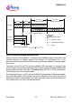
t
ECW, w.c.
= t
CW
(1+Δ)
closed window open window
t
CW
=t
CW
definition
f
OSC
=f
OSCmax
reset start delay time after window
watchdog timeout
reset delay time without trigger
reset duration time after window
watchdog time-out
t
SR
= t
OW
/2
t
OW
=t
CW
t
WDR
= t
RES
t
OWmin
f
OSC
=f
OSCmin
definition
worst cases
t
EOW, w.c.
= ( t
CW
+t
OW
)(1-Δ)
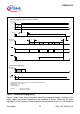
Example with:
t
CW
=128ms
Δ=25% (oscillator deviation)
t
ECW, w.c.
= 128(1.25) = 160ms
t
EOW, w.c
= (128+128)(0.75) = 192ms
t
owmin
= 32ms
(not the same scale)
t
EOW
= end of open windowt
ECW
(not the same scale)
t
OWmin
= t
OW
- Δ * ( t
OW
+ 2* t
CW
)Minimum open window time: