
Datasheet


Data Sheet 6 Rev. 2.1, 2007-08-08
TLE6258-2G
Application Information
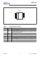
Figure 3 State Diagram
For fail safe reasons the TLE6258-2G has already a pull-up resistor of 30 kΩ
implemented. To achieve the required timings for the dominant to recessive transition of
the bus signal an additional external termination resistor of 1 kΩ is required. It is
recommended to place this resistor in the master node. To avoid reverse currents from
the bus line into the battery supply line in case of an unpowered node, it is recommended
to place a diode in series to the external pull-up. For small systems (low bus capacitance)
the EMC performance of the system is supported by an additional capacitor of at least
1 nF in the master node (see Figure 6).
In order to reduce the current consumption the TLE6258-2G offers a stand-by mode.
This mode is selected by switching the Enable Not (ENN) input high (see Figure 3). In
the stand-by mode a wake-up caused by a message on the bus is indicated by setting
the RxD output low. When entering the normal mode this wake-up flag is reset and the
RxD output is released to transmit the bus data.
TOAEA03451_1.VSD
Start Up
Power Up
ENN
Normal Mode
V
CC
Low ON
Power-Up
V
CC
ENN
RxD
High
Low
1)
High
3)
ON or
Off
ENN
Stand-by Mode
V
CC
High
ON or
Off
ENN
Wake Up
t > t
WAKE
1) After wake-up via bus
3) After start up, V
CC
ON
HighENN
LowENN
Low