
Datasheet


TLE6254-3G
Data Sheet 23 Rev. 2.1, 2007-08-09
Test and Application
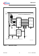
Figure 5 Test Circuits
For isolated testing the CAN Bus Substitute 1 is connected to the CAN Transceiver (see
Figure 5). The capacitors C
1-2
simulate the cable. Allowed minimum values of the
termination resistors R
RTH
and R
RTL
are 500 Ω. Electromagnetic interference on the bus
lines is simulated by switching to CAN Bus Substitute 2. The waves of the applied
transients will be in accordance with ISO 7637 part 1, test 1, test pulses 1, 2, 3a and 3b.
RTH RTL CANH CANL GND
V
CC
V
BAT
RxDNERR TxDENTWAKE NSTB INH
TLE 6254-3G
CAN Transceiver
141312111098
73654 21
R
1
1
R
C
11
CC
2
20 pF
CAN Bus Substitute 1
1
R
R
1
Schaffner
Generator
C
K
C
K
R
1
C
1,2
C
K
= 100 Ω
= 10 nF
= 1 nF
CAN Bus Substitute 2
+ 5 V
AES02423
+ 12 V
TLE6254-3G