
Datasheet


TLE6254-3G
Data Sheet 11 Rev. 2.1, 2007-08-09
When one of the bus failures 3, 5, 6, 6a and 7 is detected, the defective bus wire is
disabled by switching off the affected bus termination and the respective output stage. A
wake-up from sleep mode via the bus is possible either via a dominant CANH or CANL
line. This ensures that a wake-up is possible even if one of the failures 1 to 7 occurs.
A current limiting circuit protects the CAN transceiver output stages from damage by
short-circuit to positive and negative battery voltages.
The CANH and CANL pins are protected against electrical transients which may occur
in the severe conditions of automotive environments.
The transmitter output stages generate the majority of the power dissipation. Therefore
they are disabled if the junction temperature exceeds the maximum value. This
effectively reduces power dissipation, and hence will lead to a lower chip temperature,
while other parts of the IC can remain operating. In temperature shut-down condition the
TLE6254-3G is still able to receive CAN-bus messages.
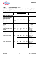
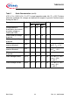
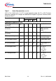
Table 3 CAN Bus-line Failures
Failure # Failure Description
1 CANL line interrupted
2 CANH line interrupted
3 CANL line shorted to V
BAT
3a CANL line shorted to V
CC
4 CANH line shorted to GND
5 CANL line shorted to GND
6 CANH line shorted to
V
BAT
6a CANH line shorted to V
CC
7 CANL line shorted to CANH line