
Datasheet


Data Sheet 10 Rev. 1.1, 2011-06-06
TLE6251-2G
Operation Modes
In Sleep mode the power supply V
CC
and the logic power supply V
IO
are usually turned off. A Wake-Up event, via
the CAN bus or the local Wake-Up pin, shifts the device from Sleep mode into Stand-By mode.
The following operations modes are available on the TLE6251-2G:
• Normal Operation mode
• Receive-Only mode
• Stand-By mode
• Sleep mode
• Go-To-Sleep command
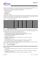
Depending on the operation mode, the output stage, the receiver stage, the split termination and the bus biasing
are active or inactive. Table 2 shows the different operation modes depending on the logic signal on the pins EN
and NSTB with the related status of the INH pin, the SPLIT pin and the bus biasing.
5.1 Normal Operation Mode
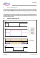
In Normal Operation Mode the HS CAN transceiver TLE6251-2G sends the serial data stream on the TxD pin to
the CAN bus while at the same time the data available on the CAN bus is monitored on the RxD output pin. In
Normal Operation mode all functions of the TLE6251-2G are active:
• The output stage is active and drives data from the TxD to the CAN bus.
• The normal receiver unit is active and provides the data from the CAN bus to the RxD pin.
• The low power receiver and the bus Wake-Up function is inactive.
• The local Wake-Up pin is disabled.
• The INH pin is connected to
V
S
.
• The RxD pin is “Low” for a “Dominant” bus signal and “High” for a “Recessive” bus signal”
• The SPLIT pin is set to
V
CC
/2.
• The bus basing is set to
V
CC
/2.
• The failure detection is active and failures are indicated at the NERR pin. (see Chapter 8).
• The under-voltage detection on the all 3 power supplies
V
CC
, V
IO
and V
S
is active.
The HS CAN transceiver TLE6251-2G enters Normal Operation mode by setting the mode selection pins EN and
NSTB to logical “High” (see Table 2 or Figure 4).
5.2 Receive-Only Mode
The Receive-Only Mode can be used to test the connection of the bus medium. The TLE6251-2G can still receive
data from the bus, but the output stage is disabled and therefore no data can be sent to the CAN bus. All other
functions are active:
• The output stage is disabled and data which is available on the TxD pin will be blocked and not communicated
to the CAN bus.
• The normal receiver unit is active and provides the data which is available on the CAN bus to the RxD pin.
• The INH pin is connected to
V
S
.
• The RxD pin is “Low” for a “Dominant” bus signal and “High” for a “Recessive” bus signal.
Table 2 Overview Operation Modes
Operation Mode EN NSTB INH Bus Bias SPLIT
Normal Operation 1 1
V
S
V
CC
/2 V
CC
/2
Receive-Only 0 1
V
S
V
CC
/2 V
CC
/2
Stand-By 0 0
V
S
GND Floating
Go-To-Sleep 1 0
V
S
GND Floating
Sleep 0 0 Floating GND Floating
Power Down 0 0 Floating Floating Floating