
Datasheet

Data Sheet TLE 6230 GP
V2.3 Page 18. Nov. 2009
6
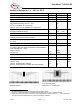
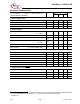
Electrical Characteristics cont.
Parameter and Conditions Symbol Values Unit
V
S
= 4.5 to 5.5 V ; T
j
= - 40 °C to + 150 °C ; Reset = H
(unless otherwise specified)
min typ max
5. Diagnostic Functions
Open Load Detection Voltage V
DS(OL)
V
S
-2.5 V
S
-2
V
S
-1.3 V
Output Pull Down Current I
PD(OL)
50 90 150 µA
Fault Delay Time t
d(fault)
50 100 200 µs
Short to Ground Detection Voltage V
DS(SHG)
V
S
–3.3 V
S
-2.9
V
S
-2.5 V
Short to Ground Detection Current I
SHG
-50 -100 -150 µA
Current Limitation; Overload Threshold Current I
D(lim) 1...8
1 1.5 2 A
Overtemperature Shutdown Threshold
6
Hysteresis
6
T
th(sd)
T
hys
170
--
--
10
200
--
°C
K
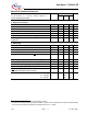
6. SPI-Timing
Serial Clock Frequency (depending on SO load) f
SCK
DC -- 5 MHz
Serial Clock Period (1/fclk) t
p(SCK)
200 -- -- ns
Serial Clock High Time t
SCKH
50 -- -- ns
Serial Clock Low Time t
SCKL
50 -- -- ns
Enable Lead Time (falling edge of
CS
to rising edge of CLK) t
lead
250 -- -- ns
Enable Lag Time (falling edge of CLK to rising edge of
CS
) t
lag
250 --- -- ns
Data Setup Time (required time SI to falling of CLK) t
SU
20 -- -- ns
Data Hold Time (falling edge of CLK to SI) t
H
20 -- -- ns
Disable Time @ C
L
= 50 pF
6
t
DIS
-- -- 150 ns
Transfer Delay Time
7
(
CS high time between two accesses)
t
dt
200 -- -- ns
Data Valid Time C
L
= 50 pF
6
C
L
= 100 pF
6
C
L
= 220 pF
6
t
valid
--
--
--
110
120
150
160
170
200
ns
6
This parameter will not be tested but guaranteed by design
7
This time is necessary between two write accesses. To get the correct diagnostic information, the transfer delay
time has to be extended to the maximum fault delay time t
d(fault)max
= 200µs.