
Datasheet
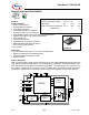
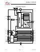
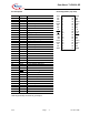

Data Sheet TLE 6230 GP
V2.3 Page 18. Nov. 2009
5
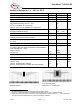
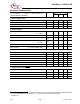
Electrical Characteristics
Parameter and Conditions Symbol Values Unit
V
S
= 4.5 to 5.5 V ; T
j
= - 40 °C to + 150 °C ; Reset = H
(unless otherwise specified)
min typ max
1. Power Supply, Reset
Supply Voltage
4
V
S
4.5 -- 5.5
V
Supply Current (outputs ON)
5
I
S(ON)
-- 1 2 mA
Supply Current (outputs OFF)
5
I
S(OFF)
-- 1 2 mA
Minimum Reset Duration t
Reset,min
10 -- -- µs
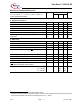
2. Power Outputs
ON Resistance V
S
= 5 V; I
D
= 500 mA T
J
= 25°C
T
J
= 150°C
R
DS(ON)
--
--
0.8
--
1
1.7
Ω
Output Clamping Voltage Output OFF V
DS(AZ)
40 -- 55 V
Current Limit I
D(lim)
1 1.5 2 A
Output Leakage Current V
Reset
= L
V
bb
=12V
I
D(lkg)
-- -- 5 µA
Turn-On Time I
D
= 0.5 A, resistive load t
ON
-- 8 12 µs
Turn-Off Time I
D
= 0.5 A, resistive load t
OFF
-- 6 10 µs
3. Digital Inputs
Input Low Voltage V
INL
- 0.3 -- 1.0 V
Input High Voltage V
INH
2.0 -- -- V
Input Voltage Hysteresis V
INHys
50 100 200 mV
Input Pull Down/Up Current (IN1 ... IN4) I
IN(1..4)
20 50 100 µA
PRG, Reset Pull Up Current I
IN(PRG,Res)
20 50 100 µA
Input Pull Down Current (SI, SCLK) I
IN(SI,SCLK)
10 20 50 µA
Input Pull Up Current ( CS ) I
IN(CS)
10 20 50 µA
4. Digital Outputs (SO,
FAULT
)
SO High State Output Voltage I
SOH
= 2 mA V
SOH
V
S
- 0.4 -- -- V
SO Low State Output Voltage I
SOL
= 2.5 mA V
SOL
-- -- 0.4 V
Output Tri-state Leakage Current
CS
= H, 0 ≤ V
SO
≤ V
S
I
SOlkg
-10 0 10 µA
FAULT Output Low Voltage I
FAULT
= 1.6 mA V
FAULTL
-- -- 0.4 V
4
For V
S
< 4.5V the power stages are switched according the input signals and data bits or are definitely switched
off. This undervoltage reset gets active at V
S
= 3V (typ. value) and is guaranteed by design.
5
For Reset = H.