
Datasheet
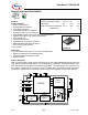
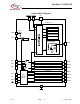
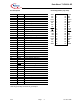

Data Sheet TLE 6230 GP
V2.3 Page 18. Nov. 2009
4
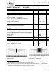
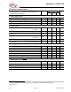
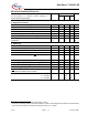
Maximum Ratings for T
j
= – 40°C to 150°C
Parameter Symbol Values Unit
Supply Voltage V
S
-0.3 ... + 7 V
Continuous Drain Source Voltage (OUT1...OUT8) V
DS
40 V
Input Voltage, All Inputs and Data Lines V
IN
- 0.3 ... + 7 V
Load Dump Protection V
Load Dump
= U
P
+U
S
; U
P
=13.5 V
With Automotive Relay Load R
L
= 70 Ω
R
I
1
)
=2 Ω; t
d
=400ms; IN = low or high
With R
L
= 24 Ω; R
I
=2 Ω; t
d
=400ms; IN = high or low
V
Load Dump
2
)
80
52
V
Operating Temperature Range
Storage Temperature Range
T
j
T
stg
- 40 ... + 150
- 55 ... + 150
°C
Output Current per Channel (see el. characteristics) I
D(lim)
I
D(lim) min
A
Output Current per Channel @ T
A
= 25°C
(All 8 Channels ON; Mounted on PCB )
3
)
I
D
500 mA
Output Clamping Energy (single pulse)
I
D
= 0.5 A
E
AS
50 mJ
Power Dissipation (mounted on PCB) @ T
A
= 25°C P
tot
3.3 W
Electrostatic Discharge Voltage (Human Body Model)
according to MIL STD 883D, method 3015.7 and EOS/ESD
assn. standard S5.1 – 1993
Output 1-8 Pins
All other Pins
V
ESD
V
ESD
2000
2000
V
V
DIN Humidity Category, DIN 40 040 E
IEC Climatic Category, DIN IEC 68-1 40/150/56
Thermal Resistance
junction - case
junction - ambient @ min. footprint
junction - ambient @ 6 cm
2
cooling area with heat pipes
R
thJC
R
thJA
5
50
38
K/W
1
)
R
I
=internal resistance of the load dump test pulse generator LD200
2
)
V
LoadDump
is setup without DUT connected to the generator per ISO 7637-1 and DIN 40 839.
3
)
Output current rating so long as maximum junction temperature is not exceeded. At T
A
= 125 °C the output
current has to be calculated using R
thJA
according mounting conditions.
PCB with heat pipes,
backside 6 cm
2
cooling area
Minimum footprint