
Datasheet

Data Sheet TLE 6230 GP
V2.3 Page 18. Nov. 2009
3
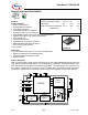
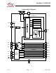
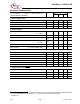
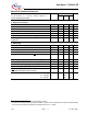
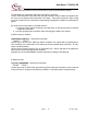
Pin Description Pin Configuration (Top view)
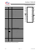
Pin Symbol Function
1 GND Ground
2 NC not connected
3 NC not connected
4 OUT1 Power Output Channel 1
5 OUT2 Power Output Channel 2
6 IN1 Input Channel 1
7 IN2 Input Channel 2
8 VS Supply Voltage
9
RESET
Reset
10
CS
Chip Select
11 PRG Program (inputs high or low-active)
12 IN3 Input Channel 3
13 IN4 Input Channel 4
14 OUT3 Power Output Channel 3
15 OUT4 Power Output Channel 4
16 NC not connected
17 NC not connected
18 GND Ground
19 GND Ground
20 NC not connected
21 NC not connected
22 OUT5 Power Output Channel 5
23 OUT6 Power Output Channel 6
24 NC not connected
25 NC not connected
26
FAULT
General Fault Flag
27 SO Serial Data Output
28 SCLK Serial Clock
29 SI Serial Data Input
30 NC not connected
31 NC not connected
32 OUT7 Power Output Channel 7
33 OUT8 Power Output Channel 8
34 NC not connected
35 NC not connected
36 GND Ground
Heat Slug internally connected to ground pins
GND 1
• 36 GND
NC 2 35 NC
NC 3 34 NC
OUT1 4 33 OUT8
OUT2 5 32 OUT7
IN1 6 31 NC
IN2 7 30 NC
VS 8 29 SI
RESET
9 28 SCLK
CS
10 27 SO
PRG 11 26
FAULT
IN3 12 25 NC
IN4 13 24 NC
OUT3 14 23 OUT6
OUT4 15 22 OUT5
NC 16 21 NC
NC 17 20 NC
GND 18 19 GND
Power SO 36